Traffic Control Plans (MUTCD)¶
Draw a work zone, right-click it, and TrafficCAD generates a complete temporary traffic control layout per MUTCD 11th Edition (Revision 1) Part 6 — advance warning, transition tapers, buffer, work space, and termination, with channelizing devices at the cited spacing, flaggers and protection vehicles, editable dimensions, and a cited compliance report. The plan is parametric: edit the zone, the road, the speed, or any override and the whole layout re-derives.
Engineering review required
Generated plans are drafts. The MUTCD (§6P.01) presents typical applications as minimum solutions to be adapted under engineering judgment — a person knowledgeable in temporary traffic control must review and approve every plan before use. The design speed is safety-critical: TrafficCAD never silently trusts it (see Speed).
Quick start¶
- Make sure the road exists as a Road markup — either vectorize the area (Auto Site → draw a box; it captures OSM lanes, one-way direction, posted speed, and road class, and splits streets into per-block segments at intersections so each block's lanes are editable on their own) or draw one with the Road tool and set its lanes/width/shoulders in Selected road.
- Draw the work zone footprint with any closed shape — Rectangle, Polygon, or Zone.
- Right-click the shape → Generate traffic control plan.
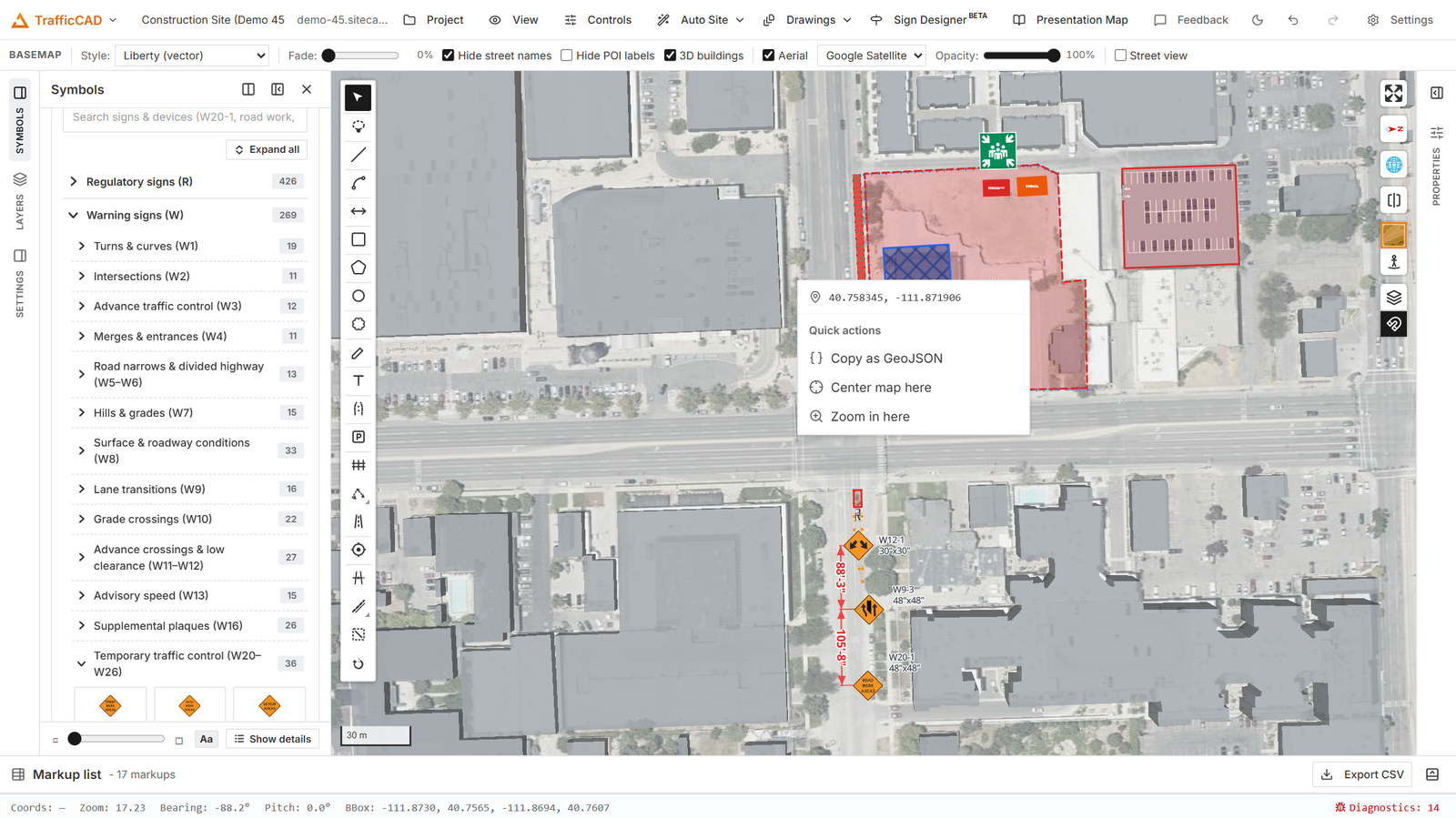
Step 3: the drawn footprint, right-clicked — Generate traffic control plan does the rest.
TrafficCAD finds the road under the zone, works out which lanes (or shoulder) it occupies and in which direction of travel, classifies the closure strategy, and swaps your shape for a TTC plan object. One Ctrl+Z restores the original shape.
Generate directly on the satellite¶
You don't need to vectorize first — right-click a zone drawn on the bare basemap or satellite imagery and generate. A spinner banner shows while TrafficCAD fetches the road network around the zone (two passes: a survey pass identifies the street and its speed/class, then the plan's true station reach — advance signs can sit a mile upstream on a freeway — is derived and the fetch re-covers that whole extent along the real alignment) and draws the Auto Site road segments, split onto their proper layers exactly like an Auto Site run — main roads on "Roads", locals on "Side streets" — so every sign, taper, and dimension lands on a drawn road segment covering the plan's full reach, each layer toggles and locks on its own, and you can inspect or edit the lanes and widths the plan derives from.
Untick Show Auto Site roads in the plan's panel whenever you want the plan to read directly on the imagery instead — the toggle hides (or re-shows) every Auto Site vector road layer at once (Roads, Side streets, and the plan's fetched road context), while the invisible roads keep driving the stationing, junction gaps, and sign placement. If a Road markup already exists under the zone, it is used as-is and nothing is fetched.
If no road can be found (offline, an Overpass rate-limit, or no mapped street), the plan is created with a "no road context" error finding — and keeps retrying on its own: the fetch re-arms after a minute, and the moment any road exists under the zone (fetched or hand-drawn) the plan links to it automatically. Generate as many plans as the job needs; each one resolves its own context.
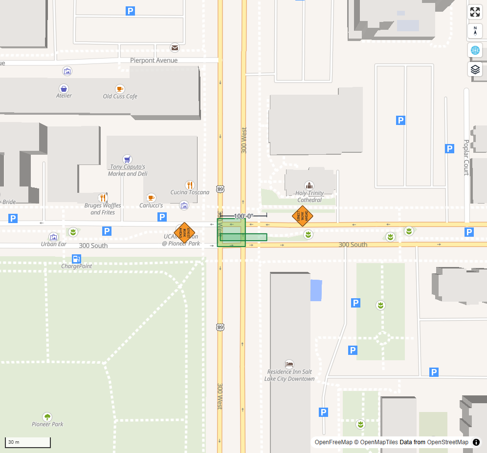
A generated plan (TA-1-style work beyond the shoulder): advance signs at the Table 6B-1 spacings, device chains, work space, and derived dimensions — all editable.
What gets generated¶
Everything below derives from the zone geometry, the road's lane configuration, and the design speed — with every number produced by the cited MUTCD rules engine (see MUTCD Rules Data):
- Signs — real, editable sign symbols from the MUTCD catalog (see Automatic signing below): the advance series at the Table 6B-1 A/B/C spacings per approach, in-zone regulatory signs, END ROAD WORK, and cross-street warnings at intersections.
- Transition area — merging (L), shifting (½L), or shoulder (⅓L) tapers per Tables 6B-3/6B-4, drawn as device chains that follow the road around curves. Shoulders ≥ 8 ft are closed with devices in advance of a merging taper (TA-33 note 3).
- Buffer space — the longitudinal buffer at the Table 6B-2 stopping sight distance (an Option you can shorten or omit; the compliance panel tells you what the table value is).
- Work space — your drawn footprint, hatched, inside the closed-lane corridor.
- Termination area — the 50–100 ft downstream taper with ~20 ft device spacing (§6B.08 ¶12), plus an END ROAD WORK anchor when enabled.
- Channelizing devices — one dashed device line per run with a device glyph at every station: ≤ 1×speed spacing in tapers, ≤ 2×speed in tangents (§6K.01 ¶04), ~20 ft in the short tapers, and ≤ S/2 where devices substitute for the center line in two-way operation (TA-32 note 3). Pick cones, tubular markers, vertical panels, drums, or barricades; device glyphs stand up as 3D meshes when the camera tilts.
- Flaggers, vehicles, arrow boards — see Protection options.
- Dimensions — real, editable dimension markups for every component, placed along the right side of the traffic flow the closure applies to (see Dimensions).
- Text — real, editable text markups for every component callout (BUFFER SPACE, MERGING TAPER L = …, DEVICES @ … O.C., vehicle tags) and the plan title with the strategy, TA citation, and design speed — each one a full Text note: select it, move it, rotate it, add leaders, change the font, or give it a fill and box outline.
- Crosswalks — wherever a drawn or imported walking path crosses the road inside the layout, a real crosswalk markup materializes on its own Crosswalks layer: open crossings gap the device lines, and crossings inside the work space are signed R9-3a CROSSWALK CLOSED (§6D). Stations that already carry a crosswalk are left alone.
How TrafficCAD reads your work zone¶
The analyzer projects the zone onto the road's centerline and measures its station extent (along the road) and lateral extent (across it), then reads the road's true cross-section at the zone — per-lane widths, any center lane (TWLTL / median / island), bicycle and parking lanes, shoulders, and turn bays active at that station — and checks every band for encroachment:
- a lane with less than 9 ft left is treated as closed (the MUTCD short-term floor, §6N.07);
- partial encroachments stay open but are width-checked;
- the affected direction(s) of travel come from the road's lane configuration (forward/reverse lanes, one-way);
- bicycle, parking, and shoulder bands are told apart, so curb work is classified by what it actually occupies;
- a zone wholly inside a turn bay closes the bay, not a through lane.
From that occupancy it picks the closure strategy automatically:
| Strategy (auto) | Typical application | Chosen when |
|---|---|---|
| Work Beyond the Shoulder | TA-1 | Zone clear of the traveled way and shoulders |
| Work on the Shoulder | TA-3/TA-5 | Shoulder occupied, no lane encroachment |
| Shoulder Work with Minor Encroachment | TA-6 | Slight lane encroachment, ≥ 10 ft lane kept |
| Lane Closure | TA-18/TA-33/TA-37 | One or more lanes of a multi-lane road closed |
| Interior Lane Closure | TA-30/TA-38 | An interior lane closed, traffic passing both sides |
| One-Lane, Two-Way Traffic | TA-10/TA-11/TA-12 | One lane of a two-lane road closed |
| Half Road Closure | TA-32 | One direction fully closed, two-way runs on the other half |
| Work in the Center of the Road | TA-15 | Center straddle with ≥ 9–10 ft open each side — including work inside a TWLTL or flush median |
| Lane Shift | TA-36 | Manual pick — full capacity carried on a shifted alignment |
| Road Closure | TA-13 | Nothing usable remains (barricade lines; plan a detour) |
| Bicycle Lane Closure | TA-47/TA-48 | Work occupying a curbside bike lane only — riders merge into the adjacent lane (W9-5a / BIKE LANE CLOSED series, R9-12 at the taper, and the R9-20 or W11-1 + IN ROAD option picked from the adjacent lane's width at ≤ 30 mph) |
| Work in a Parking Lane | TA-3 adapted | Work occupying the curb parking lane only — travel lanes stay open, parking prohibited through the zone |
| Work in a Circular Intersection | TA-52/TA-53/TA-54 | The zone sits in a drawn Roundabout: a quadrant closure flags every open approach leg (R11-2 + barricades on the legs the closure cuts off), and a multi-lane circle whose zone stays in the inner circulating lane rings that lane with devices and closes each approach's inside lane with a merging taper + arrow board |
| Sidewalk Closure | TA-28/TA-29 | A road-less zone riding a Walking path: detectable pedestrian barricades across the full walk width, SIDEWALK CLOSED (R9-9) both ends, the CROSS HERE option, and the accessibility Standards in the basis of design |
Set Strategy in the panel to override the classification; the measured lane occupancy still drives the geometry.
Two behaviors compose across strategies:
- Walking paths entering any road plan's zone get the TA-28 treatment automatically — SIDEWALK CLOSED at each point the walk crosses the zone boundary plus the detectable-barricade / audible-device Standards.
- Mobile duration swaps stationary tapers and device runs for the TA-35 protection train — work vehicle, Shadow Vehicle 1 (arrow board + TMA), and Shadow Vehicle 2 upstream — with the vehicle-mounted-device Standards noted.
The Selected TTC plan panel¶
Select the plan (click any of its zones/devices) to open the editor. The header reports the strategy, its TA/figure citation, the road, the work space length, and the device count.
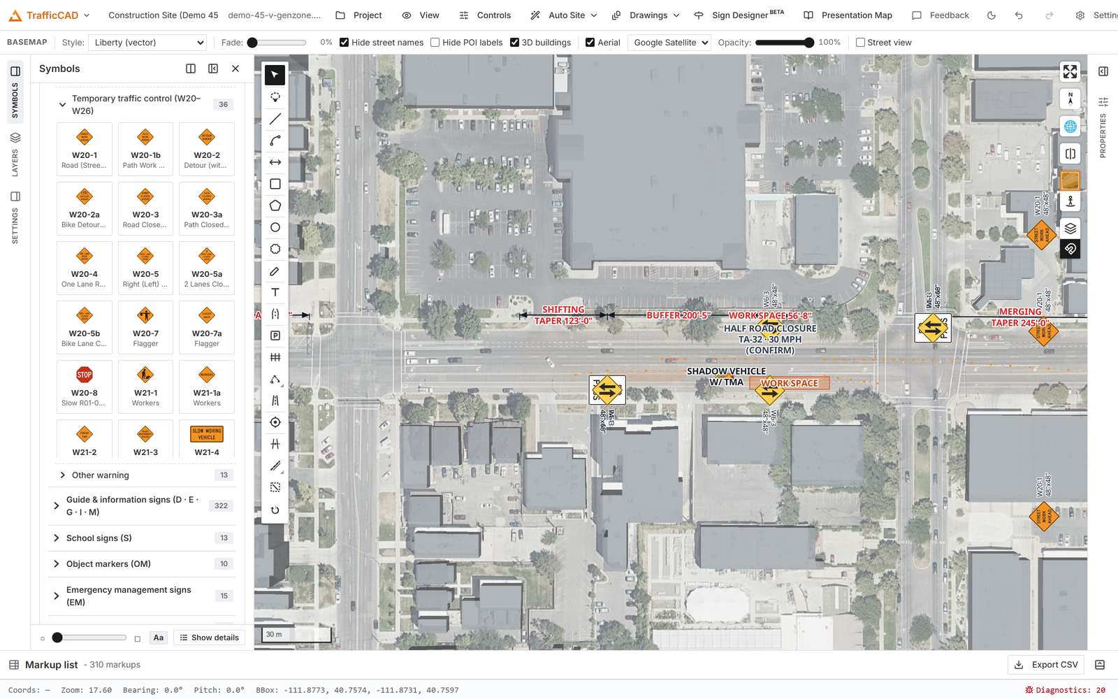
A generated plan selected: the header cites the strategy and figure, and every value below it — speed, buffer, tapers, devices — is a control with the table value as its placeholder.
| Control | What it does |
|---|---|
| Speed (mph) | Design speed for every table lookup. Inherited from the road when known. |
| Speed confirmed | Check after verifying the posted speed — clears the warning. |
| Road context | Urban street / rural highway / expressway-freeway (Table 6B-1 spacing row). |
| Work duration | §6N.01 class (long-term … mobile). Drives device-suitability checks and END ROAD WORK default. |
| Strategy | Auto (from geometry) or force a specific closure strategy. |
| One-lane control | Flaggers, temporary signal, STOP/YIELD, or self-regulating (Chapter 6E) — shown for one-lane two-way plans. |
| Devices | Cones, tubular markers, vertical panels, drums, barricades (§6K). |
| 3D devices | Stand devices up as 3D meshes when the camera tilts, or keep them flat. |
| Taper side | Direct traffic left or right around the closure (TA-21 note 2 lets turning movements drive this). |
| Buffer (ft) | Longitudinal buffer. Blank = Table 6B-2 (shown as the placeholder); 0 = omit. |
| Taper (ft) | Primary taper length override. Blank = Tables 6B-3/6B-4. |
| Downstream taper (ft) | Blank = 75 ft (50–100 range); 0 = omit. |
| Taper / Tangent spacing (ft) | Device spacing overrides. Blank = 1×S / 2×S (§6K.01). |
| Lateral buffer (ft) | Gap between the device line and the work space (engineering judgment, §6B.06 ¶15). |
| Shadow vehicle (TMA) | Optional shadow vehicle with truck-mounted attenuator in the closed lane ahead of the work space (§6B.06 ¶13 — only the area upstream of it is buffer). |
| Work vehicle | Optional work-vehicle glyph inside the work space (Table 6P-2). |
| Arrow board | Auto-required (Standard) when a freeway lane is closed — TA-33 note 7. |
| Flagger stations | Show/hide the flagger positions on one-lane two-way plans. |
| END ROAD WORK | G20-2 anchor past the termination area (defaults on for long/intermediate-term). |
| Derived dims | The plan's built-in dimension overlay — see below. |
| Sign anchors | Advance-warning sign placeholders (code + station). |
| Zone opacity | Fade the zone tints; device linework stays opaque. |
Below the controls: Basis of design (every distance and count with its MUTCD citation) and MUTCD compliance (see Compliance).
Overrides are never blocked — enter any value; if it falls below a Standard or outside Guidance, a finding tells you exactly which table or section you're deviating from.
Dimensions — selectable and editable¶
Generating a plan also creates real dimension markups — the same objects the Dimension tool draws, in the default dimension style with flat plan text — one for each component:
- MERGING/SHIFTING/SHOULDER TAPER — the transition length L,
- W — the lateral offset width the taper formula uses (Table 6B-4),
- BUFFER, WORK SPACE, DOWNSTREAM,
- A / B / C — the advance-sign spacings (Table 6B-1).
The longitudinal dimensions ride the roadside on the right side of the traffic flow the closure applies to (the reverse approach's right side when the work sits in the opposing lanes), clear of the sign line.
Because they're ordinary markups you can select, move, restyle, and relabel each one — individually, or grab the whole set at once with the panel's Select dims button:
- Move / re-seat — drag the endpoints or the offset grip; the value re-measures live (true ground distance).
- Pull the value off the line — drag the value text away and a flat-elbow leader ties it back to its dimension line (drop it back on the line to re-inline it), exactly like the Dimension tool.
- Rotate the text — the Text angle field in the Selected dimension panel sets an explicit rotation; text always flips to stay readable, and vertical text reads bottom-up. Auto returns the automatic orientation.
- Style — with the dimension selected, the markup style editor sets stroke color/width, text size/font and color, tick marks, the upright/flat label mode, and — like the Text tool — a fill and box outline behind the value text.
- Label — the Selected dimension panel edits the name that prints before the value ("MERGING TAPER = 540 ft"). Blank = value only.
- Delete the ones you don't want on the sheet.
Two supporting behaviors keep the numbers honest:
- Regenerate dims (panel button, or right-click the plan → Regenerate dimension markups) replaces the whole set from the current derivation — use it after changing the speed or strategy, re-shaping the zone, or when you want to discard your rearranging. One undo restores the previous set.
- Derived dims (checkbox) turns the plan's built-in, non-editable dimension overlay back on — handy as a check layer to compare your edited markups against the current MUTCD-derived values side by side.
Automatic signing¶
Generating a plan spawns the complete sign layout as real sign symbols (catalog artwork, individually movable/deletable, each carrying its MUTCD citation in its comments):
- Advance series per approach, chosen by strategy and condition: W4-2 + W20-5 + W20-1 for lane closures (LEFT/RIGHT artwork follows the taper side; "2 RIGHT LANES" wording on multi-lane closures), W9-3 for interior closures, W20-7/W20-4/W20-1 for flagger control (W3-3 for signal control), W21-5/W21-5a for shoulder work, W1-4 reverse curves for shifts and half-road crossovers, W20-3/W20-2 for closures. Distance legends adapt to the spacing ("1 MILE" at freeway setbacks), and the series trims on low-volume urban streets — always keeping W20-1 furthest upstream (§6H.02 ¶02).
- Both roadsides on divided/one-way highways (§6B.04) — every advance sign mirrors to the left side.
- In-zone regulatory signs: KEEP RIGHT (R4-7) at a center-work nose, TWO-WAY TRAFFIC (W6-3) and optional DO NOT PASS (R4-1) through half-road two-way sections, STAY IN LANE (R4-9) on shifts, YIELD (R1-2) for stop/yield one-lane control, ROAD CLOSED (R11-2) on barricade lines.
- Cross-street warnings at detected intersections: W20-1 on each side road approach at that road's own A distance (§6B.04 ¶08 — the TA-21…25 near-side/far-side/multi-lane intersection idiom).
- Optional signs included and marked — plaques (W13-1P advisory speed, distance plaques), END ROAD WORK, detour arrows carry an "OPTIONAL" note and can be excluded wholesale with the Optional signs toggle.
Set Traffic volume in the panel (the plan assumes HIGH until you do, and says so in the findings): low volume unlocks the low-volume typical applications, trims urban sign series, and validates STOP/YIELD or self-regulating one-lane control. Regenerate signs replaces the set after any change — one undo restores the old signs. The Derived signs checkbox overlays the current derivation for comparison, and unknown catalog codes keep their anchor placard instead of spawning.
Intersecting roads stay open¶
When another road crosses the one you're working on, TrafficCAD follows the manual's intersection idiom (TA-21…TA-27; TA-33 note 2): the channelizing device line stops at the near side of the cross street and resumes on the far side, and the taper/buffer/closed-corridor shading opens across the same span, so cross traffic is never corked by the mainline's devices. Devices redistribute within each piece at the cited spacing, tightening to the corners of the opening the way the figures show. The gap is sized from the side road's own drawn width plus a curb-return clearance on each side.
Around each detected intersection you also get, automatically:
- Cross-street ROAD WORK AHEAD signs on the side road's approaches at that road's own A distance (§6B.04 ¶08).
- A plan note at the junction station recording that the device line was opened and citing the treatment.
- A finding: an intersection inside the work zone raises a warning — the manual says additional devices shall be placed as needed there (TA-33 note 2 is a Standard), so confirm whether the side road should stay open, be closed, or get turn restrictions, and pick the matching typical application. An intersection in the advance/termination area is an informational note.
If the side road is actually closed for your operation, drag a work-zone edge across it or draw a second plan on the side road — the gap only models the open-to-traffic case, which is the manual's default.
Pedestrian crosswalks¶
Marked crosswalks (Crosswalk markups) crossing the plan road are detected the same way:
- A crossing inside the work space is treated as closed: R9-3a CROSSWALK CLOSED signs are placed on both roadside edges at the crossing, a basis-of-design note records it, and a warning finding reminds you to provide and sign an alternate accessible pedestrian route with detectable barriers (§6D.01, §6D.02).
- A crossing in the advance-warning or termination area stays open: the channelizing device line opens across the crossing band (the intersection idiom applied to pedestrians) while zone shading and point devices are unaffected, with an informational finding to verify pedestrians remain separated from the work.
Move the crosswalk or reshape the zone and the treatment re-derives live.
Protection options — flaggers, vehicles, arrow boards¶
Everything the typical applications show as an Option is a toggle, so you can match your agency's practice:
- Shadow vehicle (TMA) — drawn in the closed lane within the buffer; defaults on for lane-closing strategies. The manual counts only the area upstream of it as buffer (§6B.06 ¶13). Turning it off on a higher-speed closure surfaces an informational finding, not an error.
- Work vehicle — a second vehicle glyph inside the work space itself (the manual's legend distinguishes the two).
- Arrow board — placed just past the taper in the closed lane. On freeway lane closures it's a Standard (one per closed lane, TA-33 note 7 / TA-37 note 1): disabling it produces an error finding.
- Flaggers — one-lane two-way plans place a flagger at each end (coordinated, §6E.02), positioned by the taper on the closed side. Switch One-lane control to a temporary signal (TA-12), STOP/YIELD (TA-11), or self-regulating operation and the sign series updates.
Vehicles draw as detailed plan-view trucks (mirrors, bed equipment, the TMA's chevron cushion on the shadow vehicle) and flaggers as a recognizable person — hard hat, hi-vis vest, extended STOP paddle. Tilt the camera and all of them stand up as true 3D models, the flagger included.
Compliance — cited, never blocking¶
The MUTCD compliance list re-checks the plan on every edit. Severities:
- ● Error — a Standard ("shall") is violated or an override falls below a required value: taper shorter than Table 6B-3/6B-4, device spacing over the §6K.01 maximum, remaining lane under 9 ft, freeway closure without an arrow board.
- ▲ Warning — Guidance not met or a safety-critical assumption: unconfirmed design speed, buffer below Table 6B-2, tapers crossing a horizontal curve (§6B.08 ¶01), a side road inside the zone (TA-33 note 2), one-lane sections over a mile with flaggers (§6E.03).
- ℹ Info — Options and reminders: buffer omitted, shadow vehicle omitted at speed, 28-inch cone requirement on high-speed roads (§6K.03), short-duration simplifications (§6N.01), and the standing §6P.01 engineering-review note.
Every finding carries its citation, so the plan review writes itself.
Speed is safety-critical¶
The design speed drives everything — taper lengths, buffer, device
spacing, sign spacing. TrafficCAD inherits the posted speed from the road
(vectorized roads capture OSM maxspeed) but always flags it
unconfirmed until you check Speed confirmed. Change the speed and
the entire plan re-derives; press Regenerate dims to re-seat the
dimension markups to the new lengths.
Editing and re-deriving¶
The plan is a live parametric object:
- Drag the work-zone vertices (select the plan; grips appear on the footprint) — tapers, buffer, devices, and zones re-derive as you drag.
- Edit the road (lanes, width, shoulders, alignment — including the Auto Site road's lane editor) — every plan on it follows live, including the spawned dimension, sign, and text markups: with Auto-update markups on (the default), any road, crosswalk, or junction edit that moves the derivation re-seats exactly the kinds that changed. Your styling, value overrides, text rewrites, rotations, and drag offsets on matched markups carry over the re-seat; untick Auto-update markups to freeze everything for manual editing (the Regenerate buttons still work on demand).
- Replace the road entirely (re-run Auto Site, delete and redraw) — the plan re-links itself: whenever its linked road disappears or a road first appears under a road-less plan, the best road under the zone is adopted automatically, class/speed are inherited, walkpath crosswalks materialize, and the markups re-seat. Re-detect road remains for deliberate re-homing (e.g. after moving the zone to a different street while the old road still exists).
- Delete the plan — its generated signs, dimensions, and text go with it (a confirm explains first). Want to keep some? Convert to plain markups first, then delete just the items you don't need.
- Drag the plan freely — a selected plan always wins the press over the Auto Site road surface underneath it (and any selected markup wins over whatever paints the same pixels; the Tab overlap picker still cycles the stack).
- Undo — generation, regeneration, re-detection, and explode are each a single Ctrl+Z step.
Text — select, move, rotate, restyle¶
Every plan callout (WORK SPACE, BUFFER SPACE, taper labels, the strategy title, FLAGGER / SHADOW VEHICLE tags…) spawns as a real text markup — the same note the Text tool creates:
- Select and drag it anywhere (your offset survives re-derivation), rotate it with the rotate handle (vertical text reads bottom-up), and double-click to rewrite it.
- Restyle it like any text note — font, size, color, fill, box outline, leaders — from the style bar or the Properties panel.
- Select text in the plan panel grabs the whole set at once; Regenerate text re-seats it from the current derivation (matched notes keep your offsets, rotation, and styling).
- The Derived text checkbox overlays the plan's built-in text for comparison. Plans saved by older builds keep their drawn callouts (and the panel's legacy Callouts override list) until you press Regenerate text, which converts them into editable notes.
Dimension & callout text style¶
Dim text size / bold / color in the panel restyle the plan's derived dimension values and callouts everywhere (map, sheets, PDF). The default is a readable bold 13 px; Auto on the color returns the per-component colors. The spawned dimension markups are ordinary dimensions — style those with the standard style toolbar.
Explode to markups¶
Explode to markups (panel button, or right-click → Convert to plain markups) freezes the plan into ordinary features: zone areas, one real channelizer run per device chain (the actual channelizing-device tool — spacing stays editable, the BOM counts it, and the devices stand up as the same speed-aware 3D meshes the plan used, 18-in cones below 45 mph), flagger/vehicle/arrow-board symbols whose 3D meshes ride along (the flat plan artwork tucks away under the standing mesh when the camera tilts, so a work vehicle looks like a truck — not a decal with a truck on top), and per-piece Type 3 barricades stretched to their closure width. Your dimension and text markups stay exactly as they are. Use it for final manual staging or agency-specific tweaks the parametric plan doesn't cover; one undo restores the parametric plan.
Sheets and PDF¶
TTC plans plot as crisp vectors on sheets and in PDF exports — zone tints, device lines and glyphs, vehicle/flagger symbols, sign-anchor codes, and every dimension with its label, at true scale. Dimension labels stay readable on rotated viewports. The plan also appears in the markup list (with its TA code and zone area) and exports with the CSV.
Tips & current limits¶
- The zone is treated as station-uniform: a diagonal zone closes what its widest point closes. Draw the footprint parallel to the road for the tightest layout.
- Work zones spanning an intersection generate the standard closure plus review flags (TA-21…TA-27 corner treatments are on the roadmap); side roads near the zone are detected and flagged.
- Very short drawn roads can't carry the full advance-warning distance — the finding "extends beyond the drawn road" tells you to extend or vectorize more road.