Dimensions & Callouts
CAD-style linear dimensions that measure true ground distance — computed on the WGS84 ellipsoid in a local ground frame, accurate to better than 0.01% at any latitude, and formatted feet-inches like the drawings you're used to.
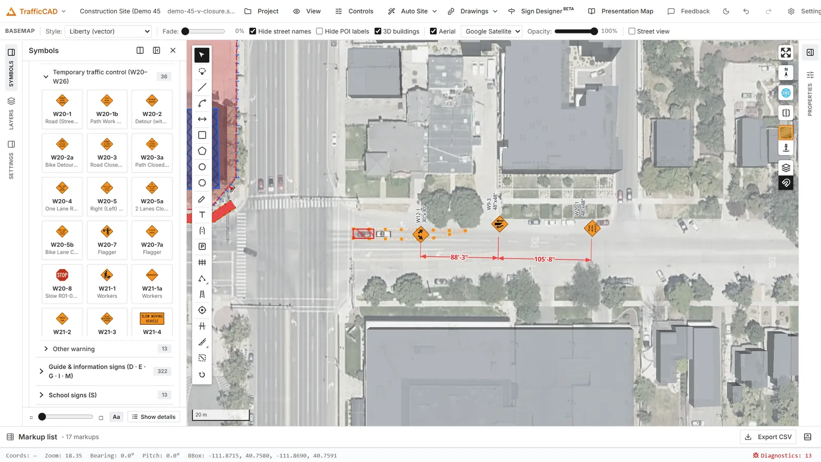
Associative dimensions on a lane closure: the taper and buffer read their true ground length, and re-measure if the devices move.
Drawing a dimension
- Pick the Dimension tool in the Traffic Control panel.
- Click the first point — snap to a sign's post, a device, a work-area corner, or the grid.
- Click the second point (hold Shift for ortho relative to the grid rotation).
- Move the cursor to drag the dimension line's offset to either side, and click to set it.
The result draws with extension lines (with the standard gap and overrun), the offset dimension line, and a halo label that never reads upside-down — flipped per CAD convention when the line runs into the lower half-plane.
Dimension labels
Every dimension can carry a label — a name that prints before the measured value, so the callout reads "MERGING TAPER = 540 ft" instead of a bare number. Select the dimension and type the name in the Selected dimension panel; leave it blank for a value-only callout. The label renders everywhere the dimension does — map, drawing sheets, and PDF exports — and shows in the markup list.
Generated traffic control plans use exactly this: each plan spawns a labeled dimension markup per zone component (taper L, W, buffer, work space, downstream, and the A/B/C sign spacings), all fully editable like any hand-drawn dimension.
Editing a dimension
Select a dimension to edit it like any markup:
- Endpoint grips re-seat either measured point (the value re-measures live as true ground distance);
- the offset grip drags the dimension line to either side of the measured points;
- the markup style editor sets stroke color and width, text size and color, tick marks, and whether the label stands upright (billboard) or drapes flat on the ground in 3D views;
- the Selected dimension panel edits the label.
Associative dimensions
When an endpoint snaps to a placed sign or device, the dimension binds to it: drag the symbol and the dimension follows and re-measures live. That's what makes device-spacing checks trustworthy while you adjust a taper.
Related
Leader lines and callouts are drawn from symbols — right-click a sign → Add leader (see Sign Display, Labels & Leaders). Generated TTC plans spawn labeled dimensions for every zone component, and dimensions plot as crisp vectors on sheets and in PDF exports.