Roads, Vectorize & Site Modeling¶
The basemap is data, not wallpaper. TrafficCAD builds an editable, true-scale model of the site for you — vectorize any view into parametric roads, sidewalks, and buildings — and gives you the tools to draw what isn't there yet: temporary roads, roundabouts, walking paths, and basemap masks.
Generate a site (Auto Site)¶
Click Auto Site in the top toolbar, then drag a box on the map around the area you want. It creates editable CAD-like layers from OpenStreetMap for the drawn area, overlaid at true scale on the basemap.
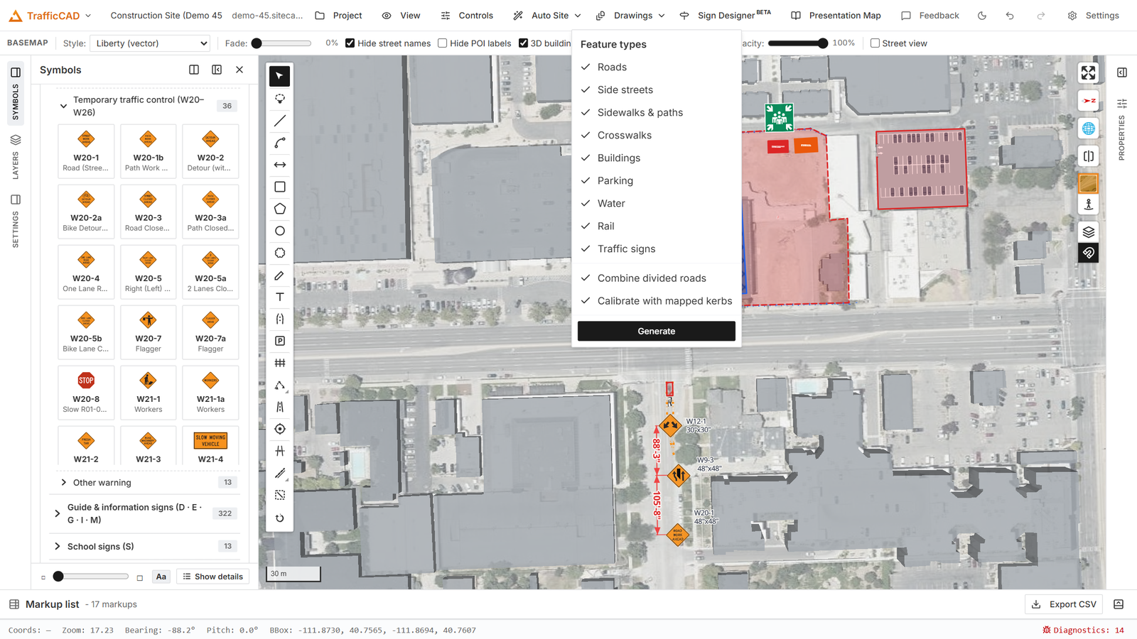
The Auto Site split button in the top toolbar: the arrow opens the feature-type dropdown; Generate starts the draw-a-box flow.
- Open the dropdown (the arrow next to Auto Site) and check the feature types you want: Roads, Side streets, Sidewalks & paths, Crosswalks, Buildings, Parking, Water, Rail, Traffic signs (all on by default). Side streets and Crosswalks are independent types: check Crosswalks with Sidewalks & paths off to import only the marked street crossings, or Side streets with Roads off to import only the neighborhood grid. Combine divided roads (on by default) merges the two one-way halves OpenStreetMap uses for a divided road into single two-way roads as they import — see Divided roads. Calibrate with mapped kerbs (on by default) measures the roads against OpenStreetMap's surveyed curb lines where a city has them — see Kerb calibration below; it does nothing where kerbs are unmapped.
- Click the Auto Site button and pick the scope: General region (current view) vectorizes everything in the current map view with no drawing — the area trims toward its center to the fetch limit, exactly like the road context a generated traffic control plan fetches for itself. Draw a specific area (also the menu's Generate button) starts the classic flow:
- Drag a box on the map around the area to convert — Esc cancels. A status banner reports progress and what was added; it warns if the drawn area covers too many km².
What arrives:
- Roads become live parametric Road markups — split into
per-block segments at every street intersection, so one block's
lanes, width, or surface edit on their own. Main roads (arterials and
collectors) land on the "Roads (OSM)" sketch layer; residential,
service, and other local streets land on their own "Side streets
(OSM)" layer, so a whole neighborhood grid toggles or locks apart
from the main roads. Vectorize captures each street's posted speed
(OSM
maxspeed), road class, per-direction lane splits (lanes:forward/lanes:backward), tagged center turn lanes (lanes:both_waysimports as a TWLTL), and on-road bicycle lanes (cyclewaytags import as parametric Ch. 9E bike lanes, with tagged widths, buffers, and contraflow direction). The TTC engine inherits the speed and class. - Every segment imports exactly as mapped — plain driving lanes with the tagged lane counts, joined to its neighbors at the shared centerline nodes, with a clean simplified centerline (straight streets arrive as straight two-point segments; vertices only where the road genuinely bends). Nothing is auto-modeled on top — no invented bays, tapers, or lanes.
- Segments align along their street the way cars actually drive it:
every block of one street imports at the same total width, and a
short approach block where one direction gains a turn lane (the
extra-
lanesway OpenStreetMap maps it as) takes that lane's room from the opposing direction (northbound 2→3 ⇒ southbound 2→1) instead of widening — so every lane line runs dead straight across every seam and only the double yellow changes slots, drawn as a smooth MUTCD transition curve inside the approach (the same curve a driver sees where a turn lane develops and the opposing lane "grows back" beyond it). A block that cannot re-balance (a 1+1 street gaining a lane) imports literally. Adjust any of it afterwards in the lane diagram — the seam transitions re-derive automatically as you edit. - Marked street crossings (
footway=crossing) become parametric Crosswalk markups on a "Crosswalks (OSM)" layer — not walking paths. The roads they cross paint the crosswalk band and anchor their stop lines against it (see Pavement markings); unmarked crossings import nothing (no paint exists on the ground). - Sidewalks & paths with centerlines become parametric Walking-path markups; plaza polygons stay as a fill layer.
- Buildings arrive as selectable area markups on their own "Buildings" sketch layer — click one to move, restyle, or delete it like any markup (the footprint name from OpenStreetMap rides in its comment).
- Parking, Water, Rail arrive as styled vector layers, grouped under "Vectorized view N" in the Layers panel.
- Traffic signs — the EXISTING signs OpenStreetMap records in the
area — arrive as ordinary, editable sign markups on a
"Signs (OSM)" layer (move, restyle, or delete them like any placed
sign; they list with their MUTCD codes in the Markups list and carry
an "Existing (OSM)" comment). Only signs surveyed into OpenStreetMap
import — nothing is invented:
traffic_signnodes with MUTCD designations (US:R1-1, state editions likeUS:CA:…/US:TX:…matched against the Sign Studio state libraries) place the exact catalog sign; semicolon-joined values (US:W1-1;US:W13-1P) become one sign assembly on one post, top panel first. Codes the catalog doesn't carry are skipped and counted in the banner — never approximated.- Speed limit signs (
traffic_sign=maxspeedwith amaxspeedvalue, orUS:R2-1) arrive with the posted number on the R2-1 face; one with no resolvable number is skipped rather than shown with a wrong default. - Stop and yield nodes (
highway=stop/highway=give_way) place the R1-1/R1-2 at the right roadside of their approach, facing the traffic they control (OSMdirectionand one-way flow are honored; an all-way stop expands to an R1-1 + ALL WAY plaque per approach). The matching stop/yield control is also set on the imported road's end — together withhighway=traffic_signalsjunctions (signal control, no sign symbol) — so those approaches render their MUTCD stop/yield bars immediately. A stop tagged ambiguously (no direction, on a multi-leg junction node) is skipped and counted — a guessed regulatory control has no place on an engineering plan.
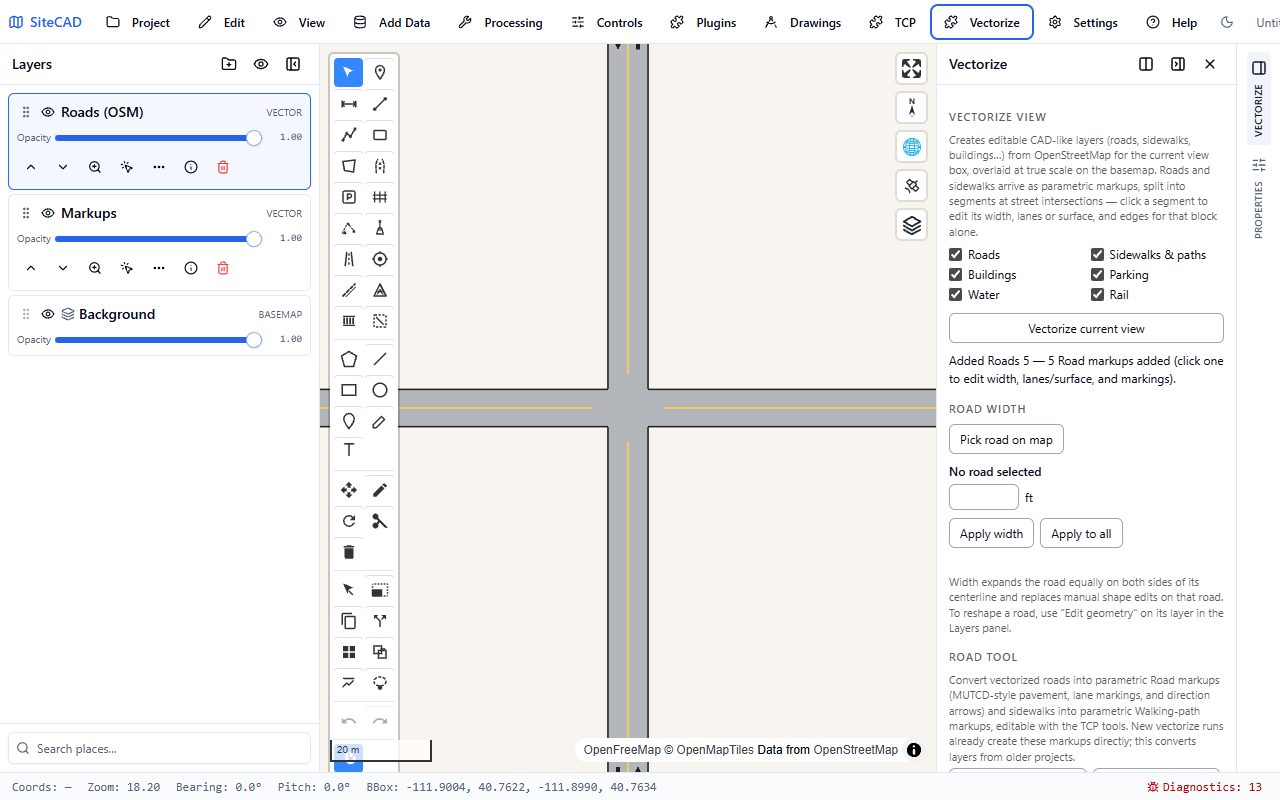
After vectorizing, streets arrive split at every junction — each block is its own editable road segment.
Divided roads (auto-combine)¶
OpenStreetMap maps a divided road as two separate one-way ways — one per carriageway. With Combine divided roads checked in the Auto Site dropdown (the default), the two halves arrive already merged into single two-way parametric roads, block by block along the corridor:
- the per-direction lane counts and widths come straight from the OSM tags of each half (2 lanes each way stays 2+2);
- the measured gap between the carriageways becomes the road's center lane, marked with plain double yellow lines — switch it to a raised island, barrier, or TWLTL in Selected road → Center lane whenever the design calls for one (the measured width is kept);
- consecutive combined blocks meet at exact shared vertices, so the corridor renders as one seamless street through every junction, and diversion or side roads drawn into a combined road clip their linework against it like any other junction — no breaks in the lines;
- roads OpenStreetMap already maps as a single two-way way are left untouched — nothing is ever split into halves.
Right-click a combined road → Separate combined road at any time to restore the original separate one-way segments exactly as OpenStreetMap provided them (one undo re-combines). Pairing is deliberately conservative — same street name/ref (or same class for unnamed roads), opposite directions, running alongside within ~150 ft — so one-way couplets a block apart never merge by accident; use the manual command below for anything the automatic pass leaves alone, or untick the checkbox to import every divided road as its two OSM halves.
Kerb calibration¶
Where a city has its curb lines surveyed into OpenStreetMap
(barrier=kerb ways), the tag-derived road widths give way to the
ground truth. With Calibrate with mapped kerbs checked in the Auto
Site dropdown (the default), each imported road samples the kerbs on
both sides along its length and — only where the survey actually covers
most of the segment:
- takes the measured kerb-to-kerb width (lane counts and every other lane definition stay with the OSM tags — the lanes just share the true pavement);
- recenters onto the kerb midline where the OSM centerline is drawn off-center;
- splits the segment where the cross-section steps (a widened approach, a dropped lane), so each piece carries its own constant measured width;
- fits the curb-return radius at junction corners from the kerb arcs and stores it per road end (see Clean junctions);
- imports closed kerb rings and
area:highway=traffic_islandoutlines as channelizing-island area markups (MUTCD 3J.03) on an "Islands (OSM)" layer — editable and deletable like any drawn marking area.
The pass is deliberately conservative: thin or one-sided kerb coverage, implausible measurements, and anything ambiguous keep the tag-derived defaults, and the status banner reports exactly how many roads were calibrated, split, or radius-fitted. Where kerbs are unmapped the checkbox changes nothing.
Combine roads¶
To rebuild a divided roadway by hand (or join segments the auto-combine skipped): Ctrl-click both halves (multi-select), right-click one of them, and choose Combine roads. The two segments merge into one two-way road in a single undo step:
- the road you right-clicked keeps its digitized direction and supplies the layer, name, and class; the other half's lanes become the opposing lanes, so the per-direction lane counts survive;
- the new centerline is the midline of the overall paved envelope, and the total width is both carriageways plus the measured gap between them;
- a gap of 4 ft or more becomes a raised median island of the measured width — switch it to a flush median, TWLTL, or barrier in Selected road → Center lane afterwards;
- outer shoulders and bicycle lanes map onto the combined road's left/right sides, and the higher posted speed wins (conservative for TTC tables).
The same command also joins two blocks of the same street that meet end-to-end (the shape junction splitting produces) into one longer segment. Combine block-by-block along a corridor — consecutive combined segments continue seamlessly across the junction nodes. Every combined road (manual or automatic) remembers its sources: right-click → Separate combined road restores them.
Split a road¶
The inverse of combining: cut one road into two independently editable segments at any point — where the lane count changes mid-block, where a turn bay should start, or to bound a work zone. Two ways:
- Split road tool (toolbar): hover any road — a blue cut line tracks the cursor across the pavement with a live station readout — and click to cut.
- Right-click a road → Split road here cuts at the clicked point.
Both halves keep the full parameter set (lanes, width, markings, speed, bike lanes, median); the original end treatments stay on the ends that remain physical ends; end-anchored auxiliary lanes follow their end; and no-passing zones and marking overrides re-station onto each half. The two halves share the exact cut vertex, so they keep rendering as one seamless street — split, then re-lane one side, exactly like vectorized junction splitting. A TTC plan linked to the road re-points to the half under its work zone. One undo restores the original road.
Edit lanes on the map (the lane diagram)¶
Select any road and its lane diagram appears: a dimension-styled cross-section drawn right on the pavement — every lane, median, bike lane, shoulder, and turn lane with its width, type, and direction of travel. The dimension lines, labels, and the drawn direction arrows (a real shaft-and-head arrow per lane) are colored by direction of travel — blue with the drawn direction, red against it — with medians, bike lanes, and shoulders in neutral slate, so the two traffic streams read apart at a glance. The diagram follows your view: pan or zoom anywhere along the selected road and the editable dimensions re-station to the stretch in front of you, so the cross-section you see is always the one under your eyes — no dragging it into place from somewhere else.
Everything about the cross-section is editable in place:
- Resize — drag any boundary tick; the adjoining lanes re-derive through the same engine as every panel edit (lane counts, medians, and tuned turn bays are preserved; the centerline re-centers so the untouched edge stays put).
- Reorder — drag a lane piece across the diagram; it snaps to the positions the road model can express. Dragging a right-turn lane across the bike lane, for example, switches between the bike lane at the curb and the MUTCD Fig. 9E-4 arrangement (bike lane between the through lanes and the turn lane).
- Add — the + buttons between lanes insert a new section: travel lane, left/right-turn lane, bike lane, shoulder, flush median, center turn lane (TWLTL), raised island, or median barrier, each at its standard width. Only the kinds valid at that position are offered. A turn lane inserts as a plain full-length travel lane with its junction assignment already set (left turns at the divider, right turns at the curb — including outside a bike lane, the MUTCD Fig. 9E-4 arrangement): the lane-use arrows, solid approach line, and lane-drop dotted marking derive at the arriving end, and inserting a second left beside the first composes a dual left automatically. No bay, no taper — where the divider consequently sits in a different slot than the neighboring segment's, the double yellow renders the smooth seam transition curve on its own. New bike lanes arrive without symbol sets (turn them on with the bike lane's Marking select).
- Retype / redirect / delete — click a lane piece to open its lane card: change the type, flip the direction of travel (on a road without a median, making a lane travel the other way moves the direction divider there — making every lane one-way converts the road), set the width, or delete the section. Bike lanes offer with-traffic / counter-flow / two-way. The card always opens inside your current view — never off-screen — and the dotted grip at its top-left corner drags it anywhere you want it.
- At junction — a travel lane's card sets its arriving movement: Left turn only, Right turn only, a shared movement, or U-turn. The lane stays a full-length straight lane while the markings update per §3B.23 — this is both how an existing through lane becomes the turn lane and what the + menu's turn inserts do for you.
Any width you type or drag is accepted — the road is never grown or shifted to keep a lane above a design minimum. Widths below common practice (9 ft travel/turn lanes, 10 ft TWLTL, 4 ft bike lanes and medians) simply flag: the diagram's width label shows an amber ⚠, the lane card notes the advisory minimum, and the Findings block in Selected road cites it — matching existing streets exactly is always possible, and the flags tell you what to verify with the governing agency.
Auxiliary lanes from older projects (turn bays, decel/accel lanes, reductions) keep their dimension assemblies: a width dimension across the lane plus a STORAGE dimension along it, each with a drag grip, and the bay card (width, storage, serving direction, turn arrows, ONLY word, delete). Their tapers always follow the MUTCD speed formula — manual taper modeling is deliberately not offered. Per-lane direction arrows stay one uniform size across the road (sized to the narrowest lane) and follow each lane's true centerline through curves.
Each edit is one undo step. The diagram can be hidden with the Lane diagram checkbox in Selected road (or the road's right-click menu) and stays out of prints and sheet captures. For a road whose cross-section steps mid-block, split it first and edit each segment.
Clean junctions¶
Roads joining and crossing render like one continuous plan, not overlapping markups:
- A road drawn into another opens its mouth: the crossing road's edge line breaks across it, markings keep the MUTCD setback, and the pavements merge seamlessly — including across the other road's shoulder or bike-lane band.
- A road that stops just short of the pavement it clearly aims at (within 12 ft) joins it anyway — no black end cap "wall" across the mouth, no background sliver.
- Two roads meeting end-to-end at a corner (a street turning at a block corner) join with a curb-return arc on the outside of the turn, a clean inside corner, center lines that run to the corner, and edge lines that sweep the return — exactly what one road with a bend would draw. Gentler joints (under 45°) stay seamless continuations, and a third leg at the same node turns the corner back into a real junction.
- Continuing segments of different widths keep their plain squared seam by default — you decide where a transition belongs. To add one, Ctrl+click two or more connected segments and press Add transition — in the Width transition panel section that appears, or straight from the right-click menu on any selected segment: every seam whose two sides are both selected gets one, so a whole corridor gains its transitions in one step. The wider block chamfers its pavement edges down to the narrower block's width over a straight taper at the seam. Remove transition (panel or right-click) returns the squared seams, and a single selected road offers per-end Add transition / Remove buttons under Width transitions. Inside a transition wedge no markings draw — the lane geometry through a width change is engineering judgment, so draw the connecting lines there manually (the pavement and its black edges follow the chamfer).
- The transition is fully editable. Select the wider road and each transition edge re-draws as a dashed red curve with handles: drag the end handle along the road to stretch or shrink the run (it snaps back to automatic near the derived length), drag the hollow midpoints to add shape points, and drag any point to bend the edge — it flows as a smooth curve through every point, so a flare or reverse-curve taper fits the real street. Shift+click a point removes it. The seam-end handle moves freely too: slide it along the road to set the taper's start back from the seam (the pavement holds the connecting road's width up to it — both endpoints of the transition adjust its extent), or pull it sideways to resize the connecting road's width (drag to matching widths and the transition dissolves into a straight-through weld). The panel adds a per-end setback field beside the length. The edge's endpoints stay derived — the seam end from the neighbor's width, the far end from this road's own — so transitions always reconnect when either segment is re-edited. The same controls live in Selected road → Width transitions (length and setback per end, Straighten, Reset to automatic sizing, Remove to delete the transition), and the edited shape carries to the 3D view, Drawings viewports, and PDF exports.
- Direction arrows are selectable objects. With the road selected, every per-lane travel arrow is grabbable: drag one to reposition it anywhere on the pavement (it keeps following the road's curvature and stays put however the striping re-derives), Shift+click hides it. Selected road → Direction arrows reports the edits and Restore all arrows returns every arrow to its automatic row.
- Every junction mouth gets curb-return fillets: instead of the square notch two offset bands make, each corner where a road end meets another road's edge sweeps a tangent arc — the rounded corner real intersections have. The radius defaults by road class (urban 15 ft, rural 30 ft, expressway 50 ft) and is fully yours: set Curb return (ft) per end in Selected road → Intersection (0 restores square corners); where two ends meet, the corner takes the smaller of the two radii. Auto Site fits the radius from surveyed OSM kerb arcs where mapped.
Parametric roads¶
Draw new roadways with the Road tool (click the centerline, Enter to commit) — a detour, haul road, or replacement alignment rendered at true ground width with MUTCD-style pavement, markings, and direction arrows. Select any road (drawn or vectorized) to open Selected road:
| Control | Notes |
|---|---|
| Total width (ft) / Lane width | Lane width is derived (total ÷ lanes). Lane-count edits keep the lane width and let total width follow. |
| Lanes forward / reverse | Reverse = 0 makes it one-way. |
| Direction | Two-way / One-way. |
| Center marking | Double solid yellow, broken yellow, one-direction no-passing (§3B.01), or none. |
| Center lane | None, Two-way left-turn lane (§3B.05), Flush median island (§3J.03), Raised median island (curbed) — concrete or grass, with rounded noses set back from the junctions — or Median barrier (concrete), each with its own width. Raised islands and barriers stand up in 3D when the camera tilts. |
| Lane lines | Broken white / solid white / double solid white / none. |
| Edge lines / Shoulders | Edge line toggle; left/right shoulder widths. |
| Arrows | Lane direction arrows with adjustable spacing. |
| Surface / opacity | Paved or gravel; fade the surface to let imagery read through. Opacity applies to every connected or overlapping road surface at once — continuing segments, cross streets at junctions, and touching roundabouts fade together, so junction patches never render half-faded. |
| Posted speed (mph) | Drives every TTC table lookup on this road. |
| MUTCD context | Urban street / rural highway / expressway-freeway. |
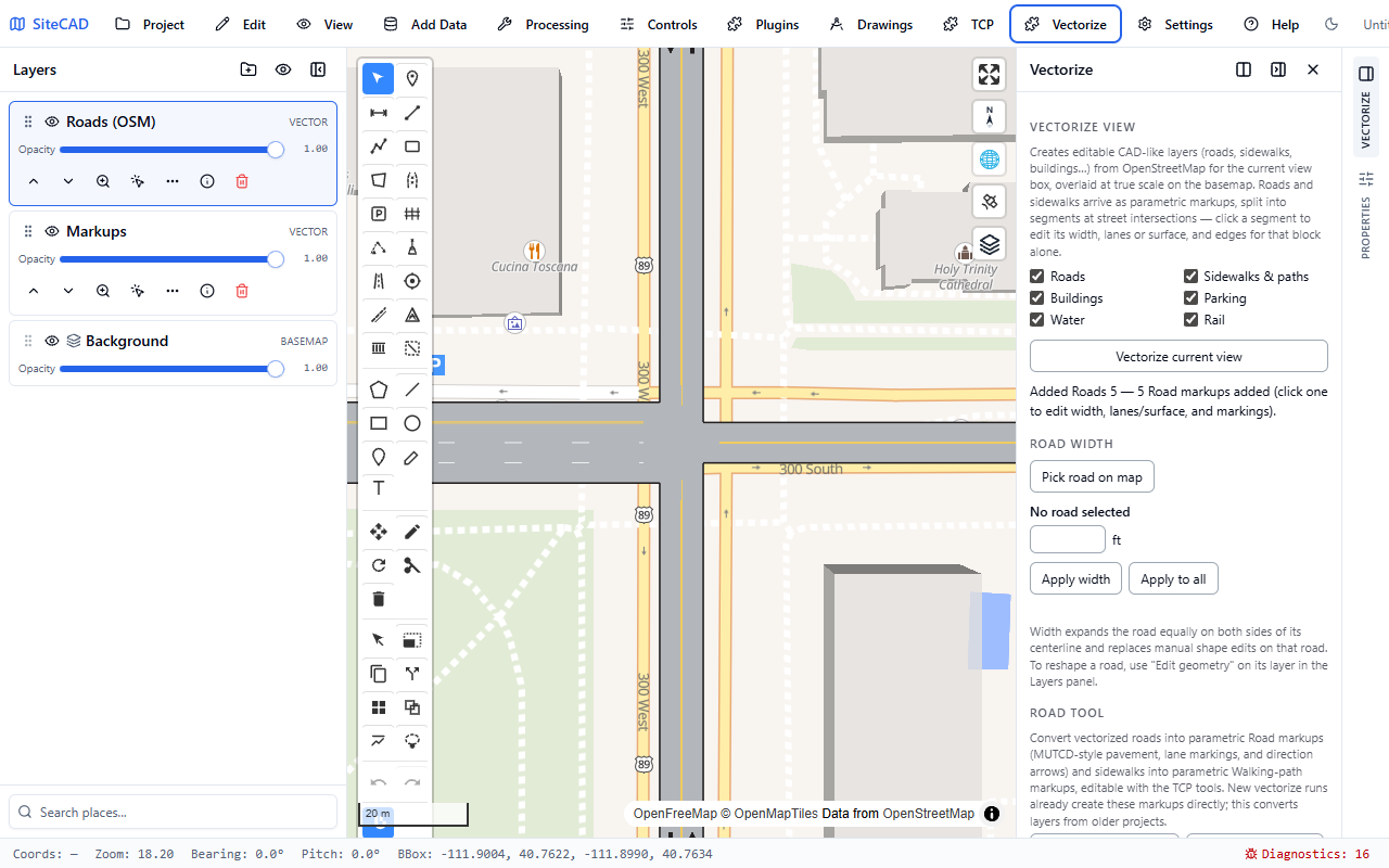
One vectorized block re-laned in Selected road — the pavement, markings, and arrows re-derive parametrically without touching the neighboring blocks.
Bicycle lanes (MUTCD Chapter 9E)¶
Each side of the road can carry a bike lane: width, direction (with traffic, counter-flow, or two-way bikeway), buffer with auto/diagonal/ chevron hatching (§9E.06), tubular-marker separation (§9E.07), marking style (symbol + arrow, BIKE LANE words…), marking spacing, and green pavement (§3H.06). Bike symbols and words are the real Figure 9E-1 glyphs at ground scale.
Intersection treatments¶
Per end of the road segment (End A / End B), pick the Control — stop
line, signal, or yield triangle row — plus a crosswalk in any of the
four Figure 3C-1 styles, lane-use arrows with optional ONLY words
(type the lane list: left, through, right), and dotted line
extensions through the intersection. The marking
engine draws all of it junction-aware.
Turn lanes — the plain-lane model¶
A turn lane is a full-length travel lane with a junction lane-use assignment, not a tapered bay: insert Left-turn lane / Right-turn lane from the lane diagram's + menu (at the divider boundary for lefts, at the curb side for rights) and the lane arrives with its left/right arriving assignment already set — lane-use arrows, the solid approach line, and the lane-drop dotted marking all derive at the junction end. Adding a second left beside the first composes a dual left automatically. Because Auto Site splits roads at every junction, the segment is the approach; where the divider consequently sits in a different slot than the neighboring block's, the double yellow draws a smooth transition curve across the seam (see Roads below). Manual taper modeling is deliberately not offered — it produced more errors than it prevented.
Auxiliary lanes¶
Add deceleration / acceleration lanes (§3B.07), wide-dotted
auxiliary lanes, and lane reductions (§3B.12) — anchored to
either end, serving either direction, with speed-formula tapers
(L = WS / WS²/60, always derived from the posted speed) and optional
ONLY words. Cited findings flag non-standard values. Turn bays from
older projects keep rendering exactly as saved (including
median-carved Figure 3B-14 bays); their width and storage stay editable
here and on the bay card.
Editing individual marking segments¶
Every longitudinal line a road derives — center lines, lane lines, edge lines, bay lines, bicycle-lane lines — is individually selectable: Alt+click a marking segment on the map and the Lane marking properties open for exactly that piece. The focused segment edits like a line markup: two end grips appear on it — drag either end to slide that end's station (the From/To range follows live, materializing an override on a derived line). Ctrl and Shift keep working while Alt is held — they act on whatever else is under the cursor when no marking line is hit (and a Shift+click on an overlapping vertex grip still deletes the vertex). Pick the Type (single solid, single dashed, double solid, double dashed, or the mixed solid-and-dashed doubles — each in white or yellow, plus dotted lane / extension cadences), and adjust the painted Width (in), double-line Separation (in), Dash length (ft) and Dash spacing (ft), or the exact From/To stations. Split segment arms a one-shot click that cuts the line where you click, so different ranges of one line can carry different types; Hide segment erases paint over the range; Reset to derived returns the road's own striping. Each edit is a per-segment override listed under the road's Marking overrides (select or remove them there); overrides survive road edits and end-to-end combines, and print identically on sheets and PDF.
The Split marking toolbar tool is the standing version of that one-shot split: with it active, click any derived marking line to cut it right there — no need to select the road or arm anything first. The click also focuses the downstream piece, so the Lane marking panel opens ready to restyle it; Alt+click either half afterwards to keep editing. Double-click the tool button to pin it and split several lines in a row.
Convert to editable polygon¶
The Convert button explodes a road into plain geometry: the pavement polygon, each marking as its own polyline, and painted symbols as filled polygons — for the agency-specific tweak the parametric road can't express. Parameters are lost; one undo restores the parametric road.
Road AI calibration¶
OSM widths are guesses — a mapped width when someone measured it, else
lanes × 12 ft, else a per-class default — and real pavement is routinely
several feet off. Road AI measures the actual road from aerial
imagery and proposes calibrated parameters for the vectorized Road
markups: curb-to-curb and travel-way width, lane count, center
/ lane / edge lines (color and pattern read from the paint), bike
lanes, parking, and stop lines / crosswalks at the segment
ends (with their Figure 3C-1 style).
How it works: each road's centerline is resampled into a rectified corridor strip (one pixel column per ground station), Gemini reads the strip through a structured measurement schema, and every reported edge or line is then snapped to the strongest local pixel gradient — the model finds the feature, the pixels supply the sub-pixel precision. Stations inside cross-street openings are excluded, occlusions (parked cars, tree canopy) are flagged, and per-station widths pass a robust median/MAD filter before anything is proposed.
Use it from the Road AI toolbar menu — Measure roads in view
(AI) or Measure selected roads (AI) — or open the Road AI
panel: paste a Gemini API key (stored on this device; the Settings → AI
GEMINI_API_KEY also works), pick the measurement imagery (Esri
World Imagery, Google Satellite, USGS NAIP) and model, then Measure
selected / Measure roads in view. Free-tier keys are paced
automatically (~1 road / 7 s), and a batch run measures at most 40
roads per click.
Nothing applies automatically. Each road gets a review card: the measured strip with the detected edges drawn on it, a confidence badge, the proposed changes ("Width 24 → 37 ft", "Center line: none → double-yellow"…), and warnings (heavy occlusion, parking, mid-block crosswalks, implausible lane widths). A cyan/dashed overlay on the map shows exactly what was detected, station by station. Apply takes one road, Apply all takes every confident proposal in a single undo step; low-confidence cards are held back from Apply all and apply only per-road after you eyeball the strip. When the mapped centerline rides off the true lane center, the card offers Recenter path — interior vertices shift onto the measured alignment while segment ends stay put, so junction connectivity is never torn.
Measurement notes for plan production: widths are relative pixel measurements inside one strip, so they hold to roughly a pixel (±0.3–0.5 ft on Esri/Google imagery) even where the imagery's absolute georegistration drifts; absolute position inherits the provider's registration like every other capture. Imagery dates vary by provider — re-measure after a restripe, and treat flagged low-confidence blocks (dense parking, tree cover) as field-verify items.
Roundabouts¶
Place with the Roundabout tool (click the center). Parameters: Inscribed diameter, circulating width, truck apron, circulating lanes (1–3), landscaped or paved island, arrows, and surface opacity. The center-island diameter is derived and shown.
Walking paths¶
The Walking path tool draws parametric paths: width (m), surface (paved, gravel, trackway/matting, grass, woodchip), left/right edges (edge line, rope line, barrier, fence), one-way flow with arrows, and an Accessible flag that warns when the path is too narrow for two-way wheelchair passing. Paths merge at junctions like roads, and convert to editable polygons the same way.
Covered walkway. Tick Covered (canopy) for a construction covered walkway (protected pedestrian route): the plan draws dashed overhead roof outlines with support posts at every frame module, and in 3D (tilt the camera) the canopy stands up as a full roof-and-post structure over the path.
Temporary routes in the roadway. When a temporary pedestrian route runs in the street, set the traffic-side edge to Barrier — it draws as a heavy line in plan and stands up as chained 6-ft longitudinal barrier sections in 3D (positive protection between pedestrians and traffic). A Fence edge stands up as a chain-link run. Both open exactly where paths merge, like the drawn edge lines. Pair barriers with Covered (canopy) for a fully protected walkway.
Masking the basemap¶
The Mask tool paints over the basemap in land color — hide an existing road you're detouring around, a building, or a label so your replacement geometry reads cleanly. Masks render under every markup and bake into sheet captures (that's their job). Draw the polygon, Enter to commit.
Where this leads¶
Vectorized roads are what make the rest of TrafficCAD automatic: the TTC generator reads their lanes, speed, and class; pavement markings restripe when you re-lane; and sheets plot roads as true-scale vector linework.