Skip to content

Create a Traffic Plan

Build a traffic control plan the way the demo video does: place the work area and truck, run a channelizer taper, swap cones for drums, add and customize signs, draw dimension lines, and check mounting and scale in 3D. About seven minutes.

The recording this tutorial follows (7:04). Every screenshot below is a step from it.

1. Position the work area and truck

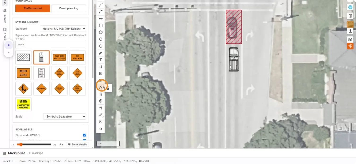
Zoom in on the section of roadway where you will create the traffic plan. The symbol library on the left carries the full National MUTCD (11th Edition) sign catalog.
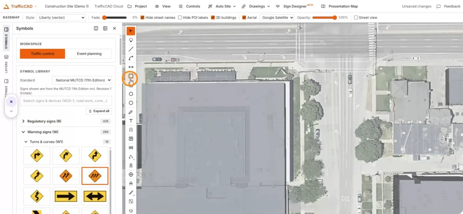
The TrafficCAD workspace with the MUTCD symbol library open over aerial imagery

Draw the work area with the rectangle tool, then place the truck at the desired location.
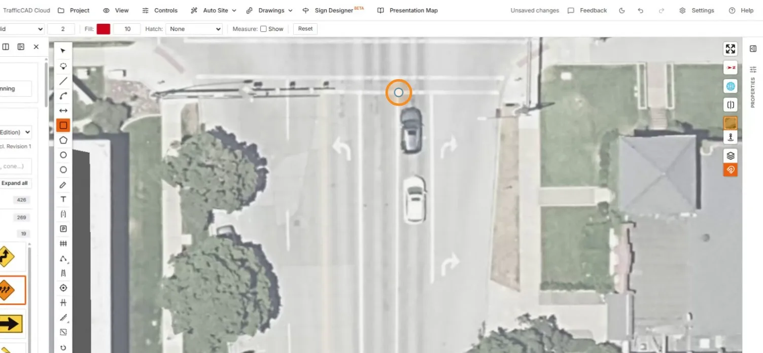
The rectangle tool active, ready to draw the work area on the roadway

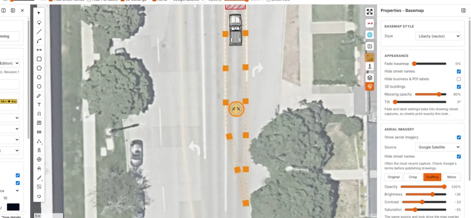
A red hatched work area and work truck placed in the closed lane

2. Add channelizing devices

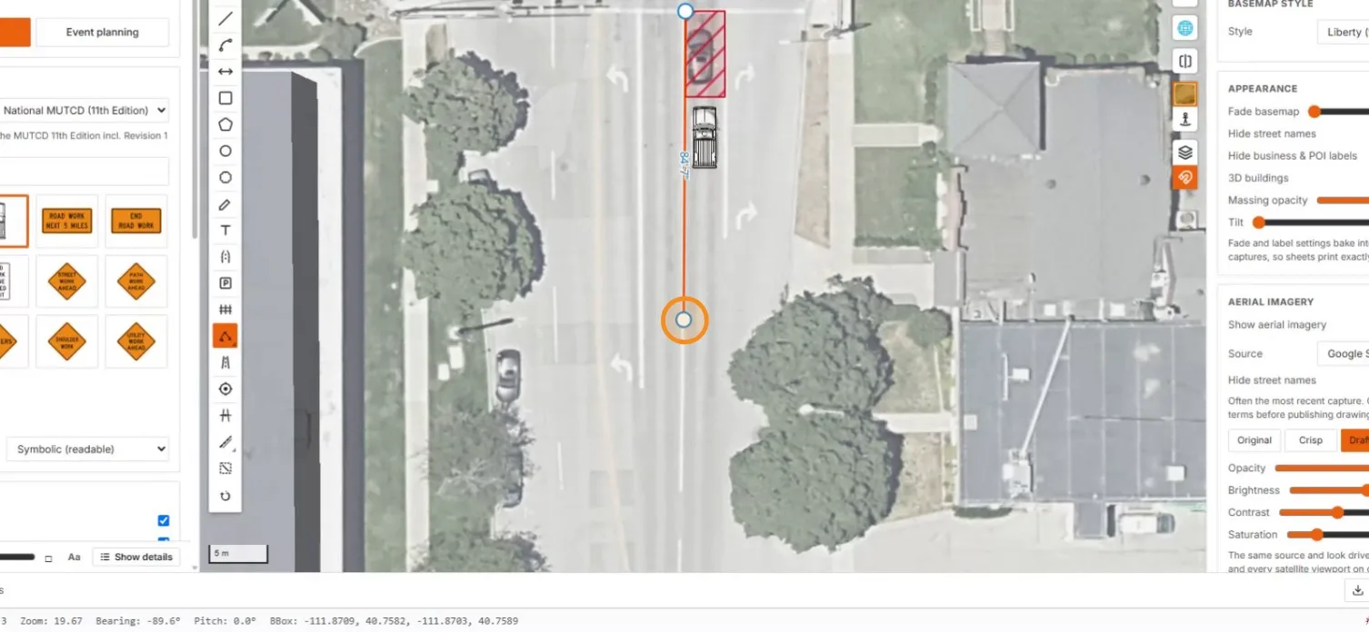
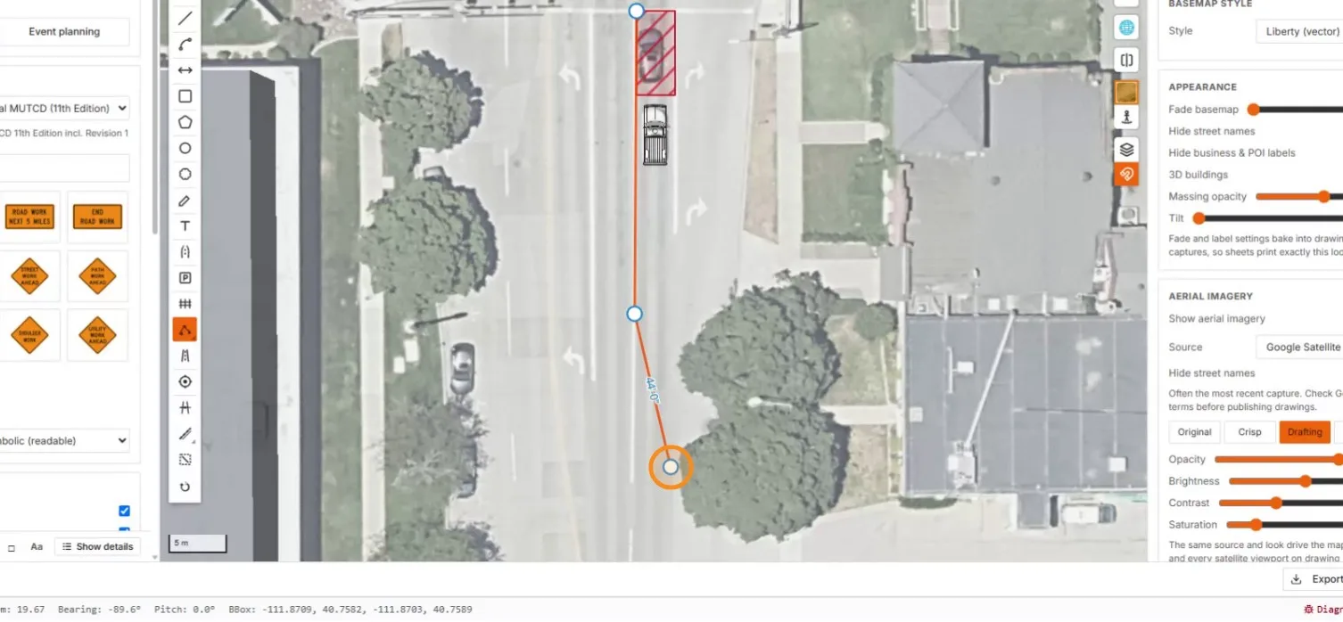
Pick the channelizing-device tool and click the taper out from the truck along the lane.
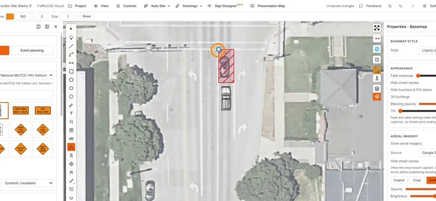
The channelizing-device tool selected in the drawing toolbar

The first cone segment drawn from the truck with a live length readout

The cone line extended through a second vertex toward the intersection

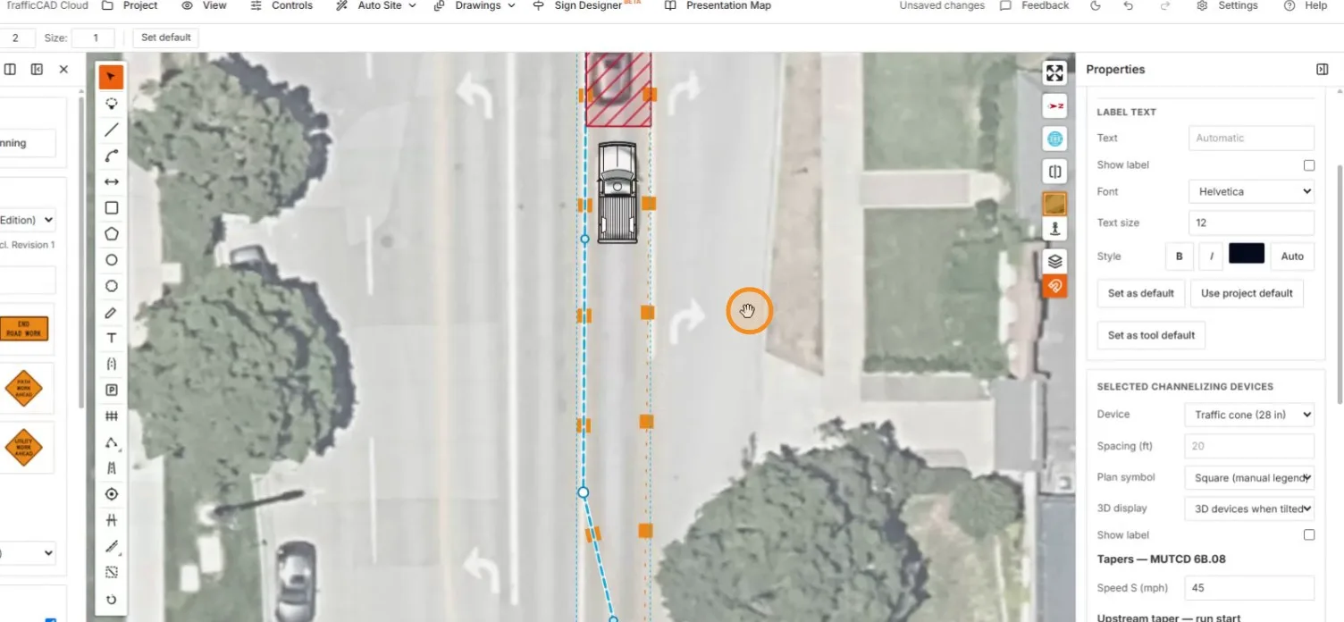
Select the finished run: the panel shows the device, spacing, and the MUTCD 6B.08 taper settings for the posted speed.
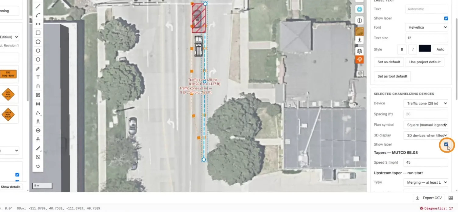
The completed cone run selected, with MUTCD taper properties and per-device spacing

3. Clean up the view and go 3D

Device labels can be turned off when they clutter the plan.
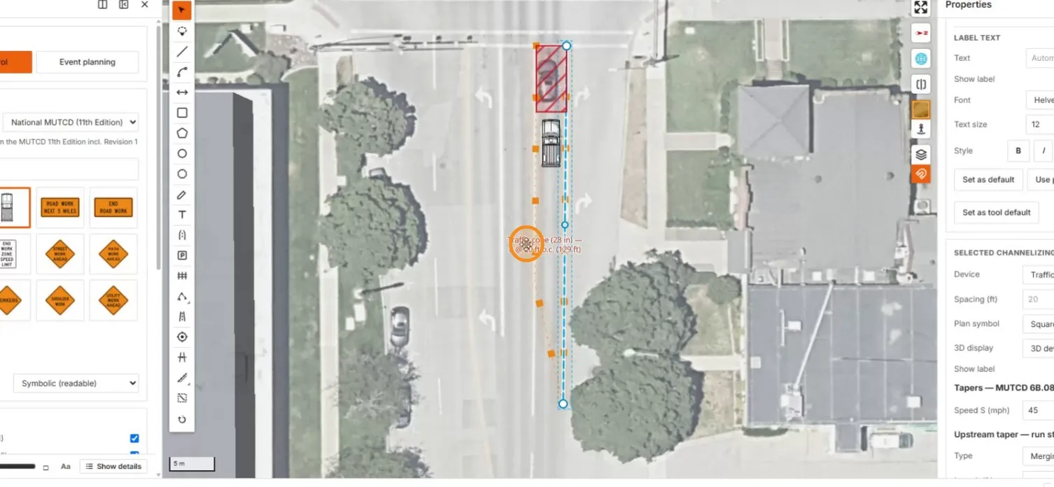
The cone run's label under the cursor before hiding it

The taper with labels hidden — clean square cone markers only

Tilt into 3D to review the plan in three dimensions — the truck, work area, and cones all stand up.
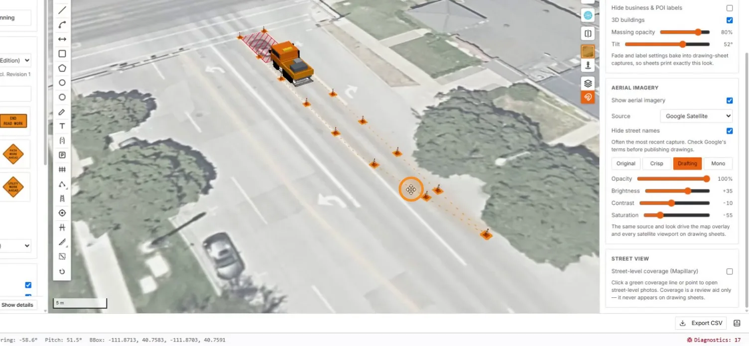
A tilted 3D view with the work truck and traffic cones along the taper

4. Swap the device type

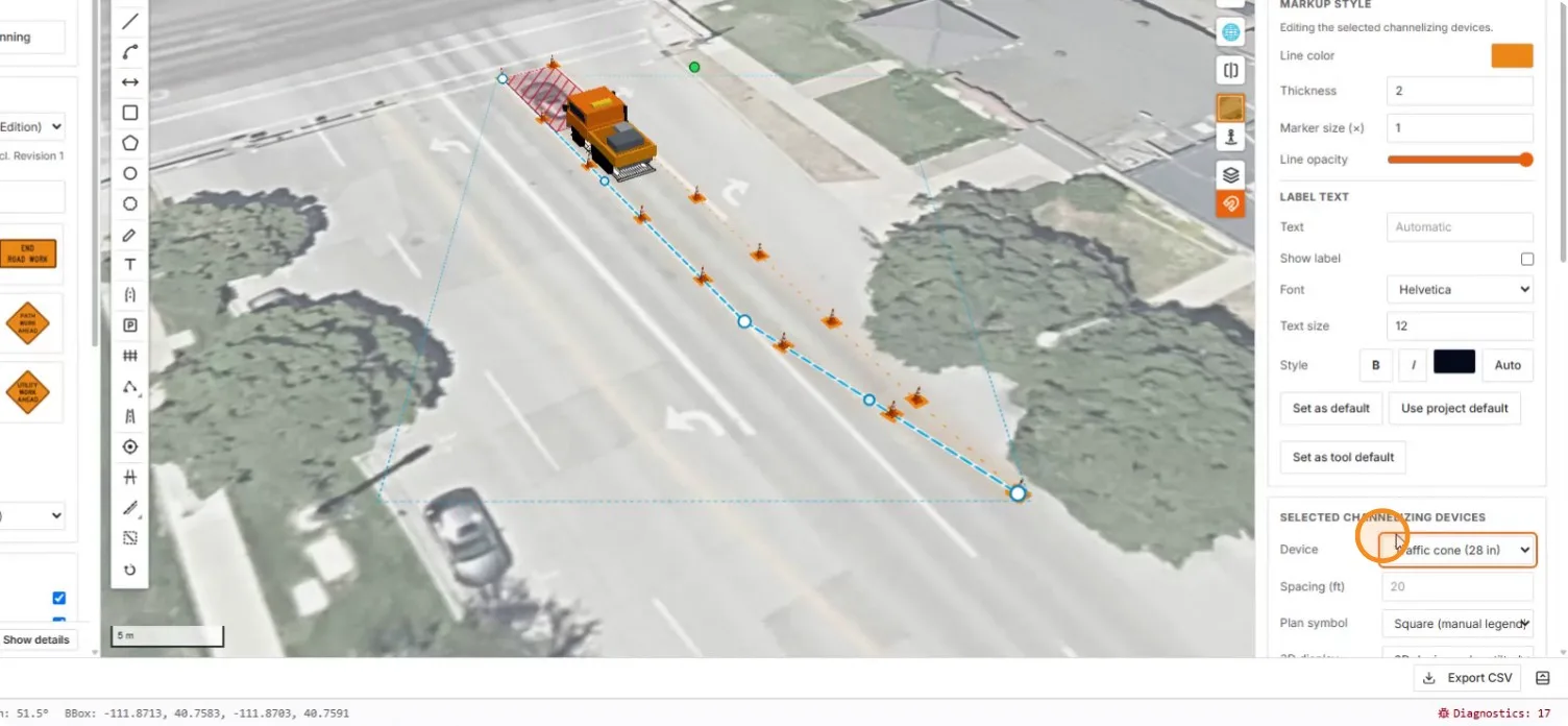
The Device dropdown on the selected run switches every device in the taper at once.
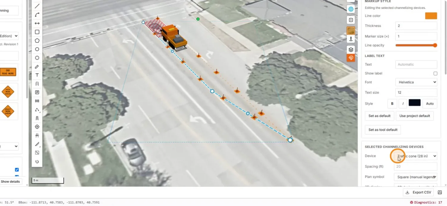
The Device dropdown on the selected run, reading Traffic cone 28 in

The same dropdown focused, ready to change the device

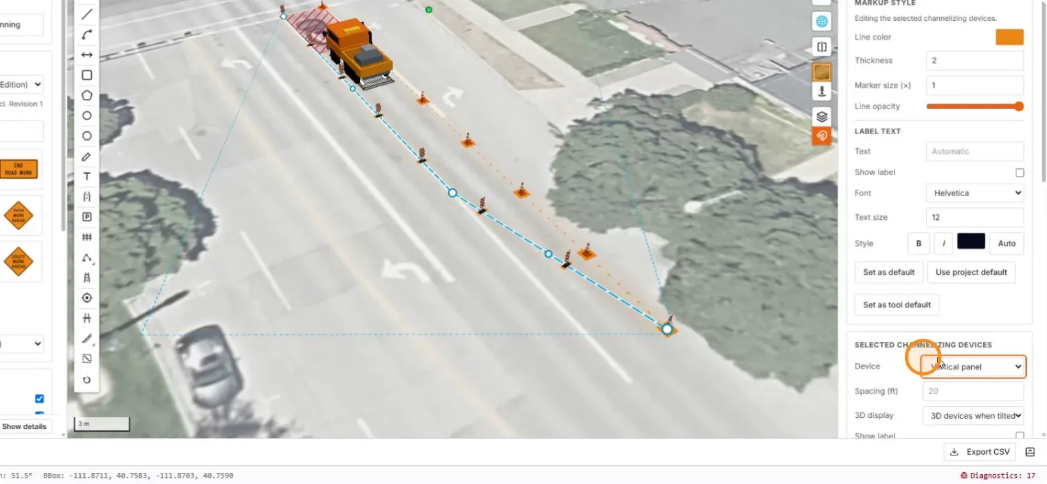
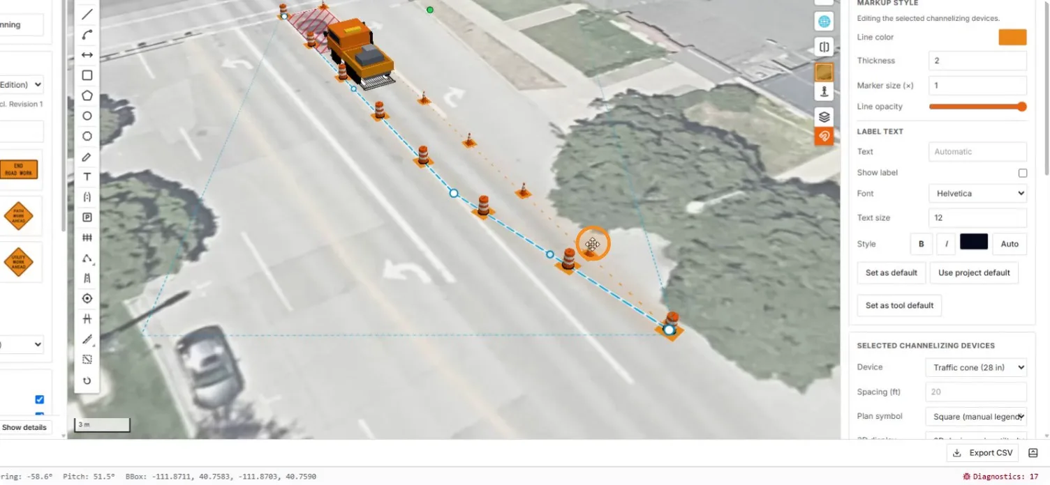
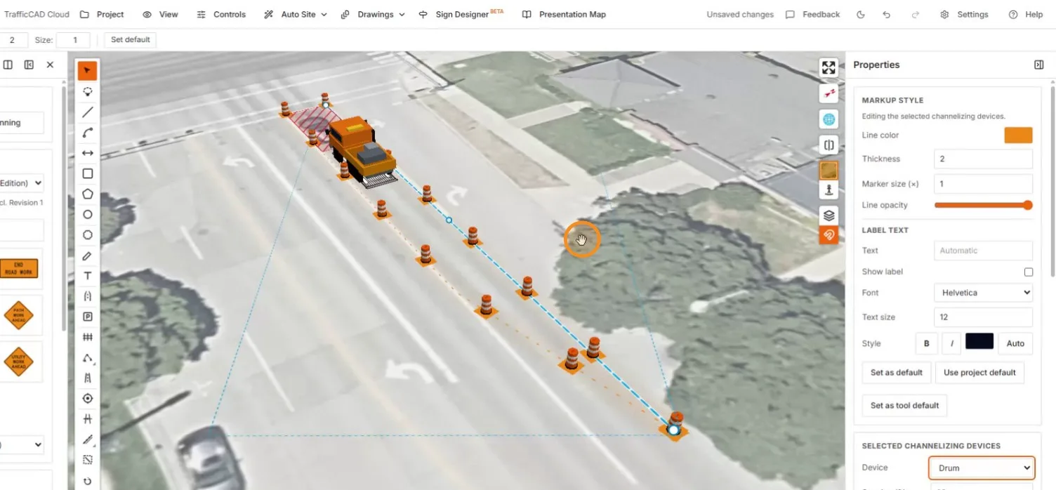
Try the options — 18-inch day cones, vertical panels, drums — the 3D view updates live.
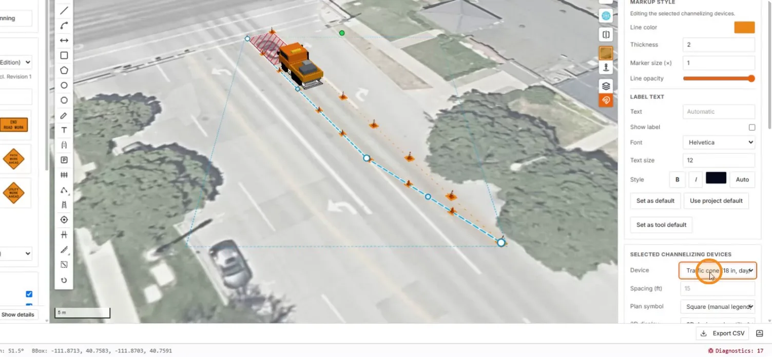
The run switched to 18-inch day cones at 15 ft spacing

Striped vertical panels rendered along the taper in 3D

Drums appearing along the taper as the device changes

The finished drum taper behind the work truck in 3D

5. Add and customize signs

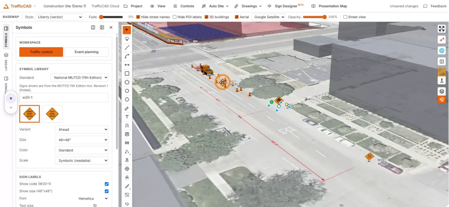
Search the symbol library — by name or MUTCD code — and place signs straight onto the plan.
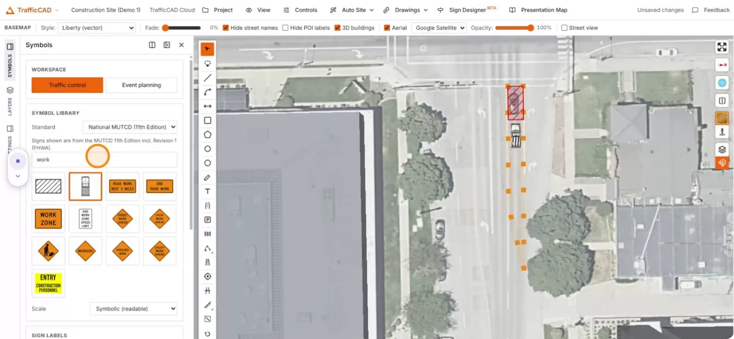
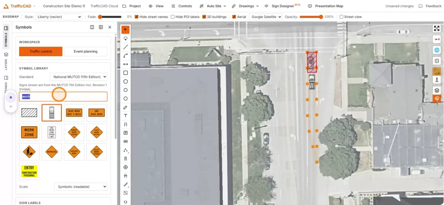
Searching "work" in the symbol library with work-zone sign results

The search text highlighted for a new query

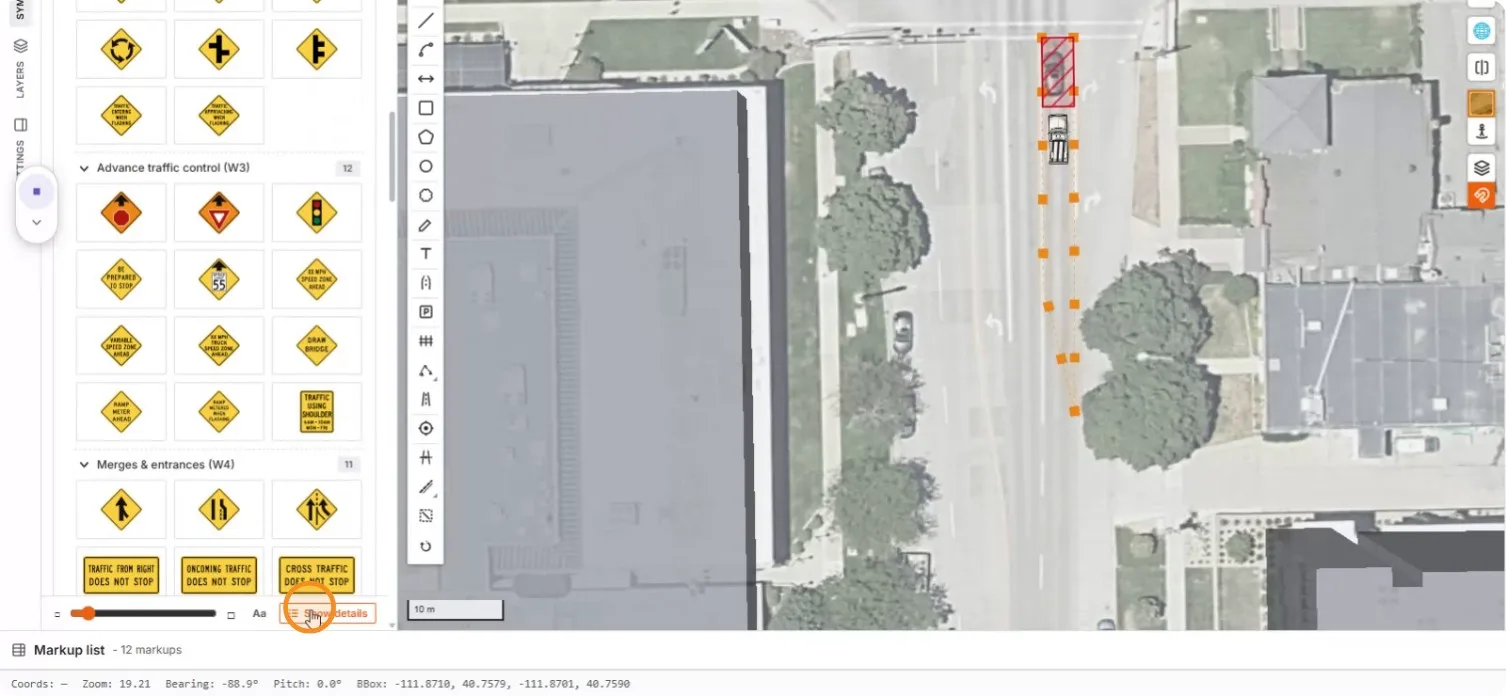
Browsing the Advance traffic control and Merges & entrances categories

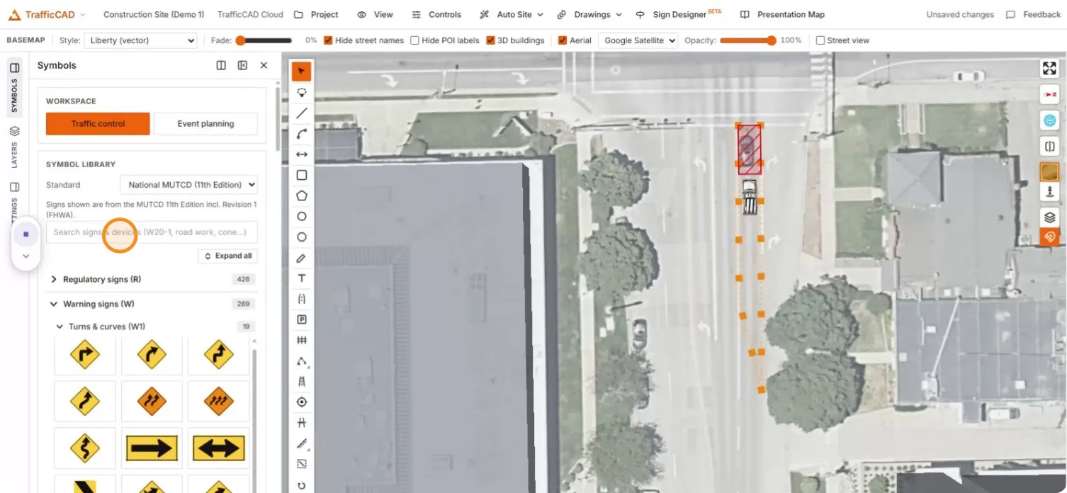
The library at category level — 426 regulatory and 269 warning signs

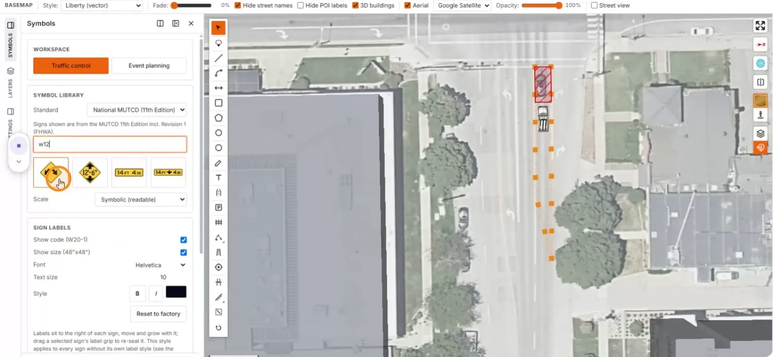
Searching "w12" and picking the W12-1 double-arrow sign

The W12-1 ghost preview being placed inside the taper

Every sign's artwork colors can be remapped — keep the standard colors or process them per project.
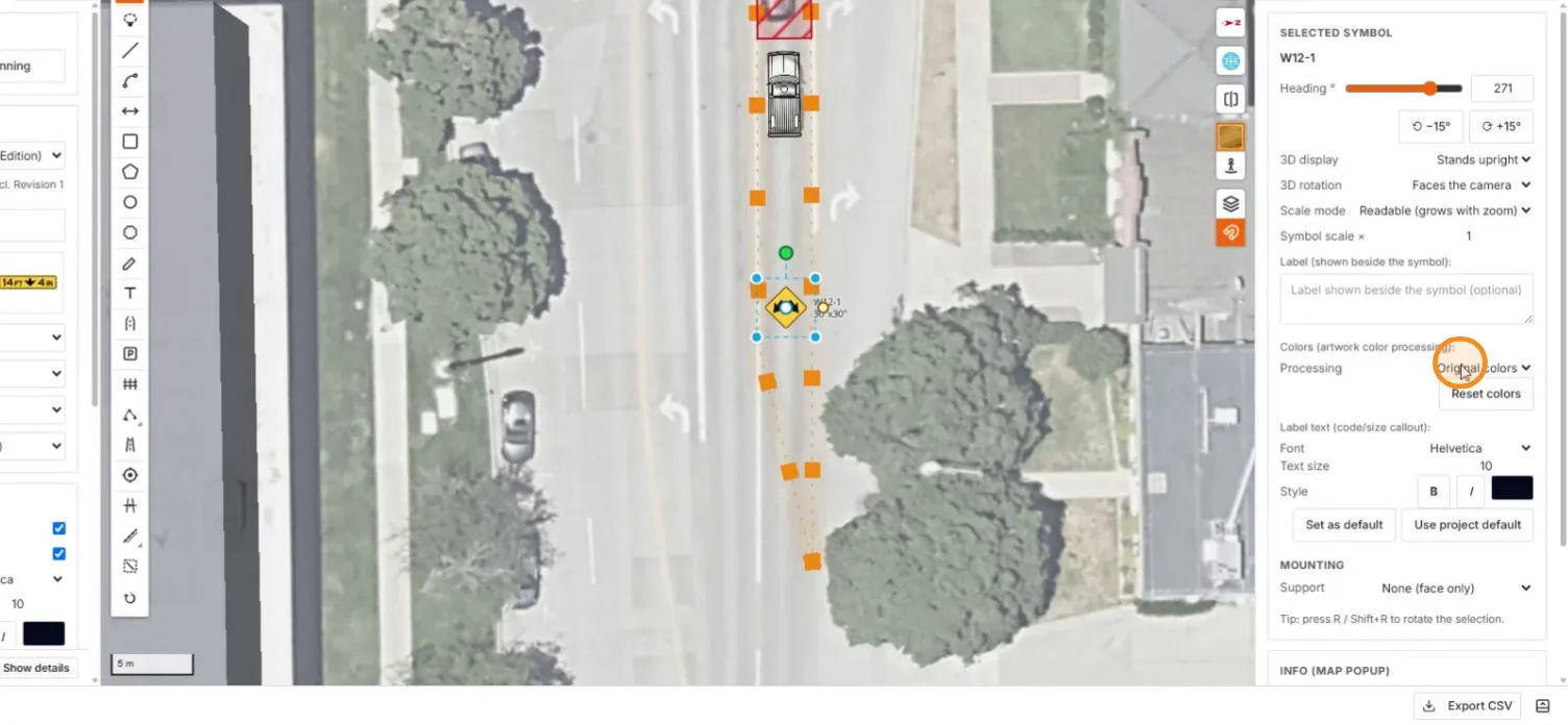
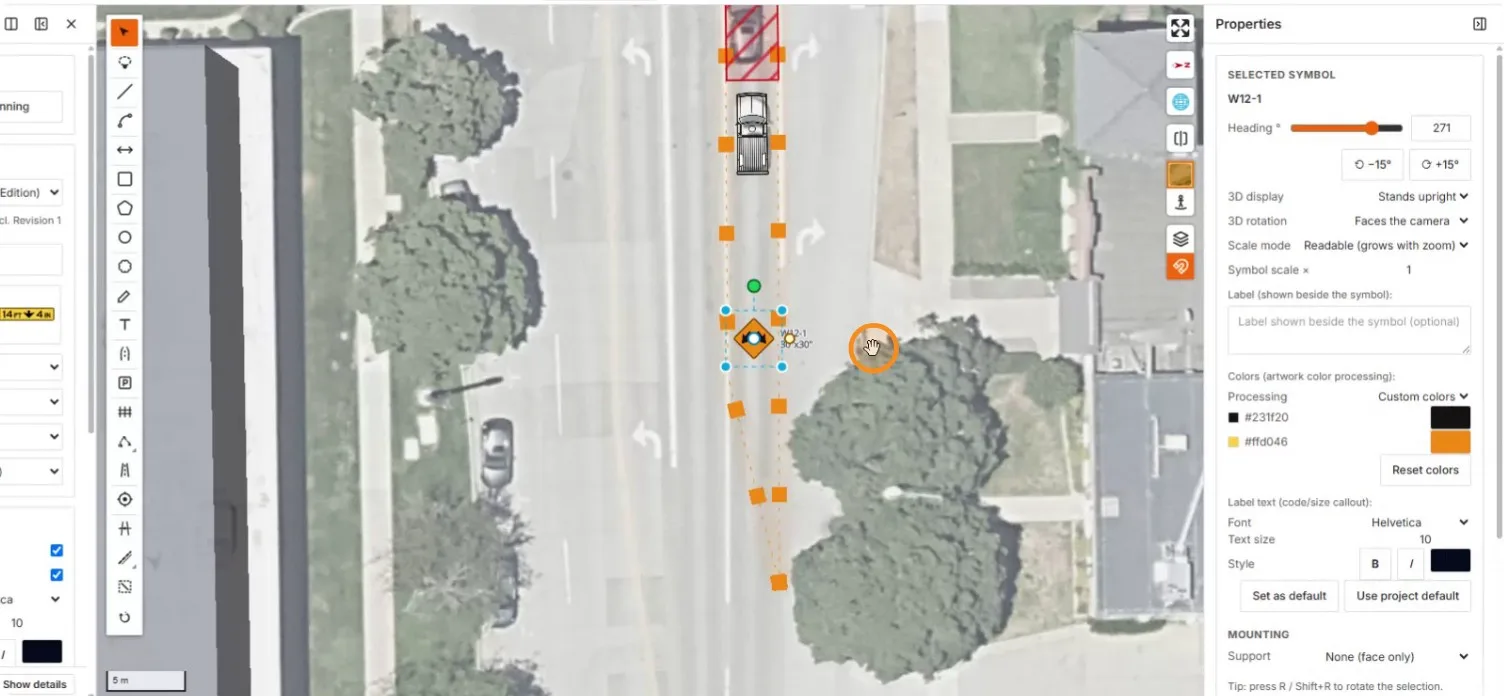
The placed W12-1 sign with the original-colors processing option

The W12-1 recolored through custom color processing

6. Draw dimension lines

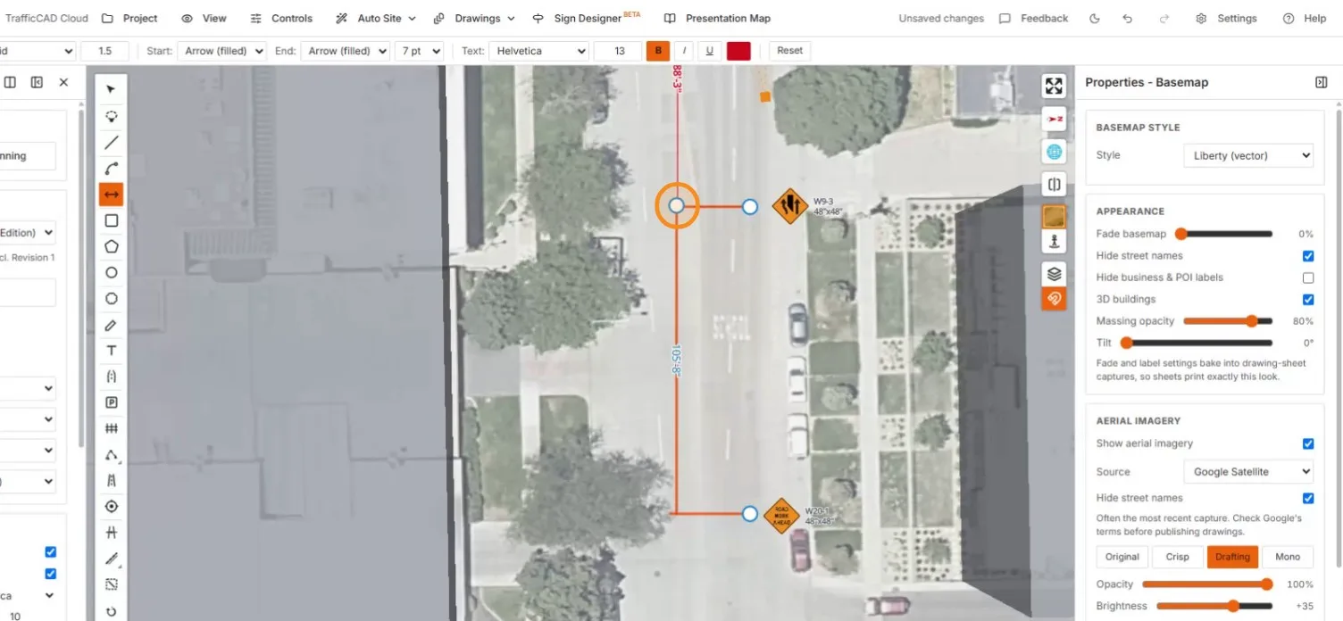
Dimension lines document taper length, buffer space, and sign spacing.
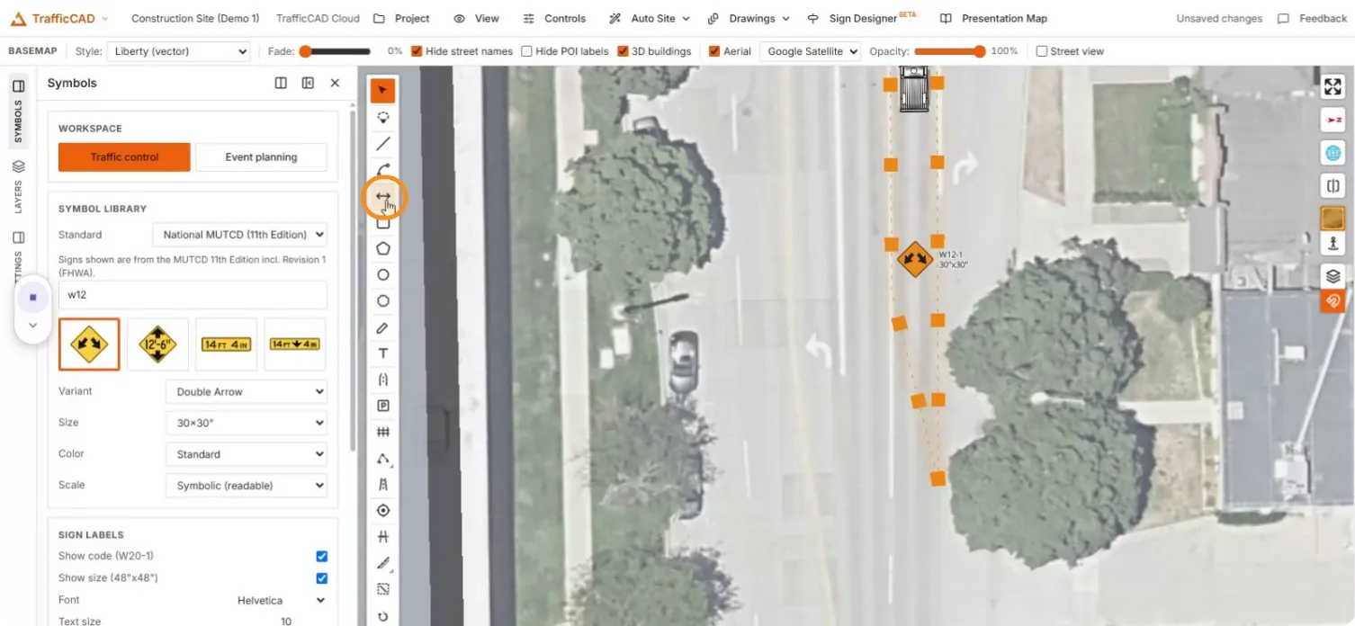
The dimension tool selected in the drawing toolbar

The first red dimension line drawn along the roadway

A second dimension between the signs records their spacing.
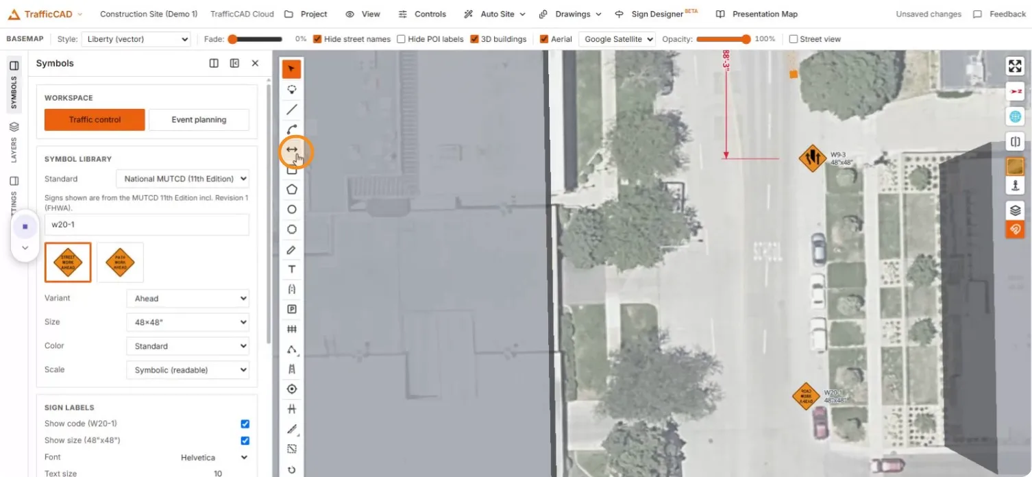
Selecting the dimension tool again for the sign-spacing dimension

Dragging the 105'-8" dimension between the two warning signs

7. Edit sign text

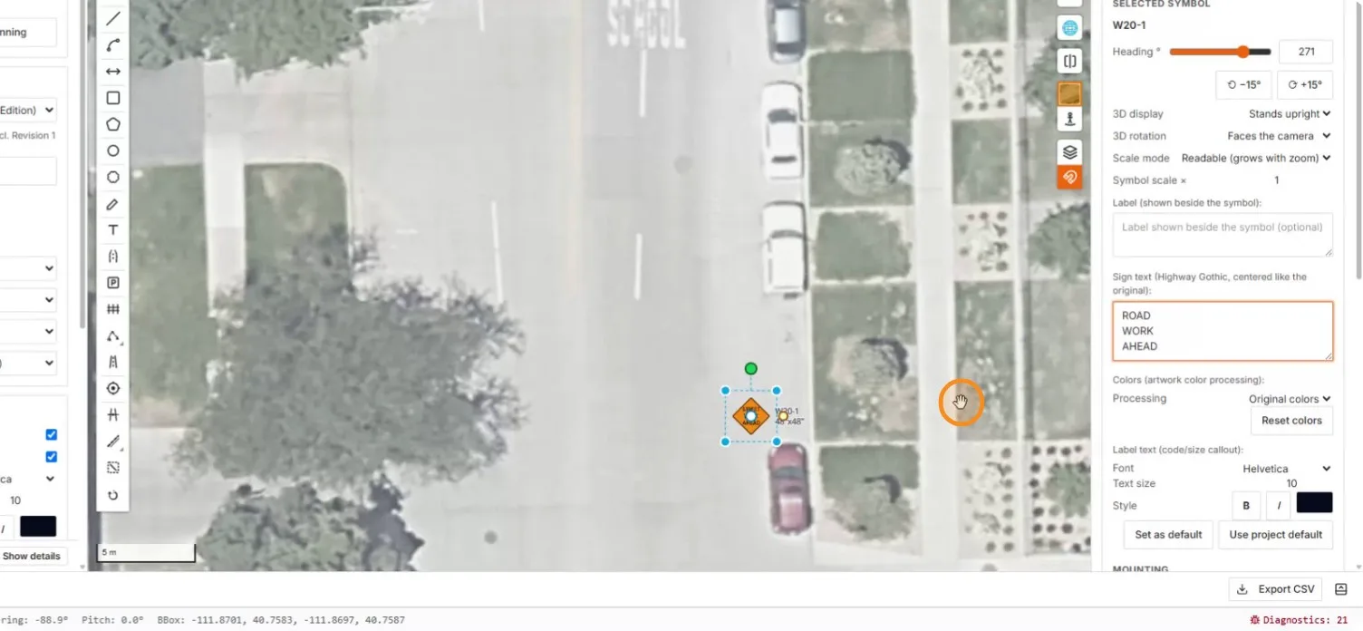
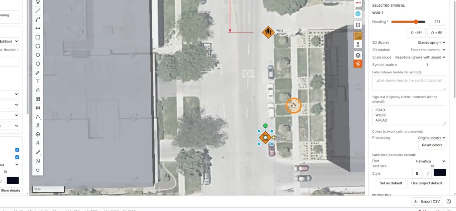
Select any sign to edit its legend — the sign face updates on the plan as you type.
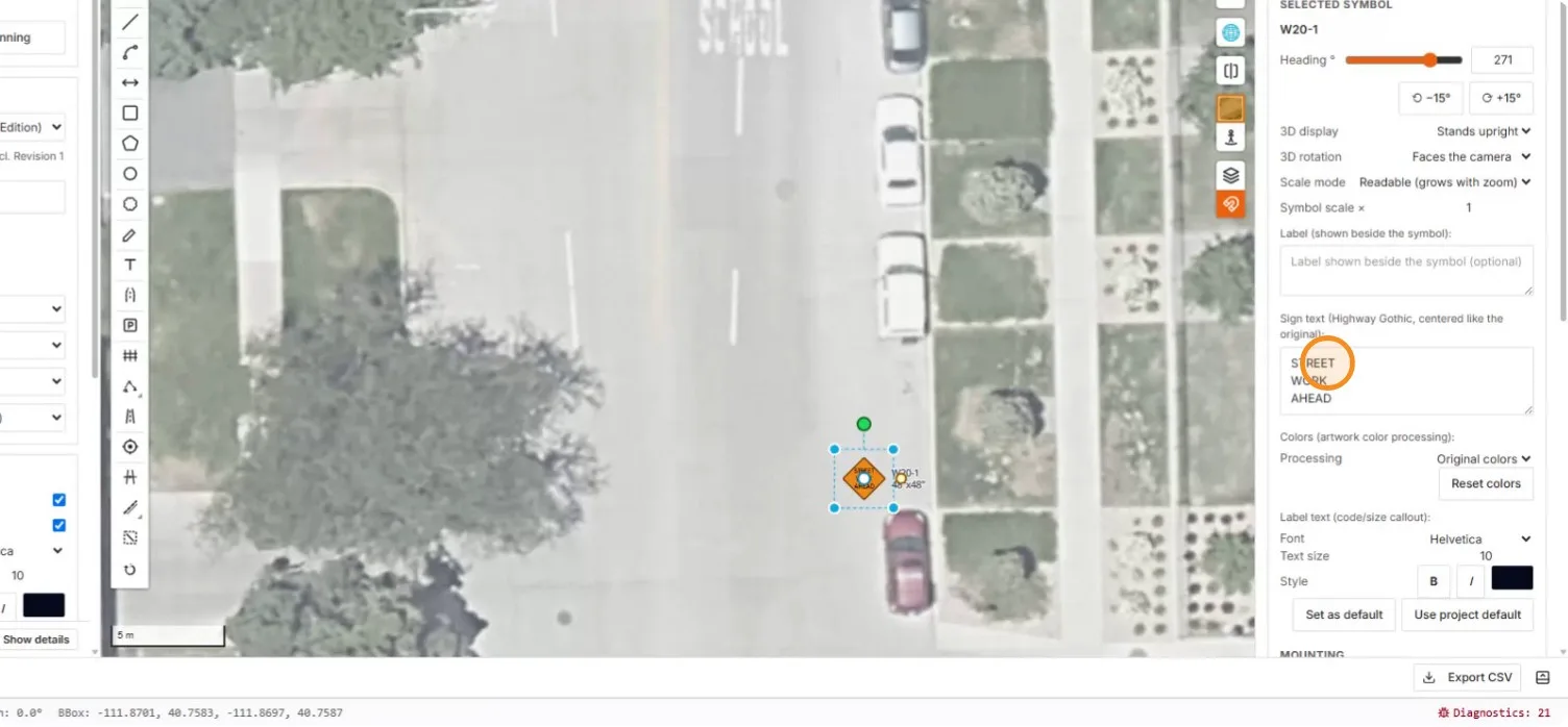
The selected W20-1 with its editable sign text field

The text changed to ROAD WORK AHEAD and applied to the sign face

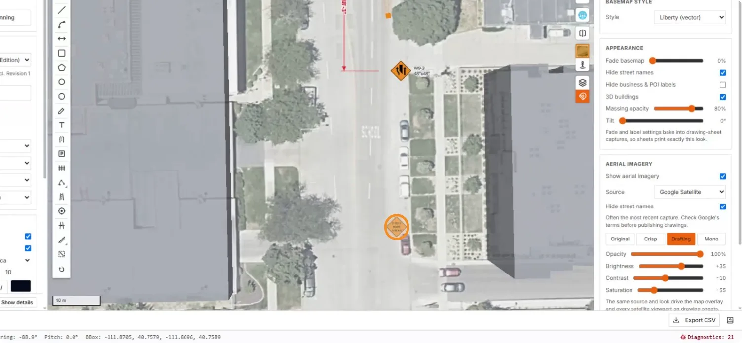
The plan with the W9-3 and the edited ROAD WORK AHEAD sign

8. Review in 3D and configure supports

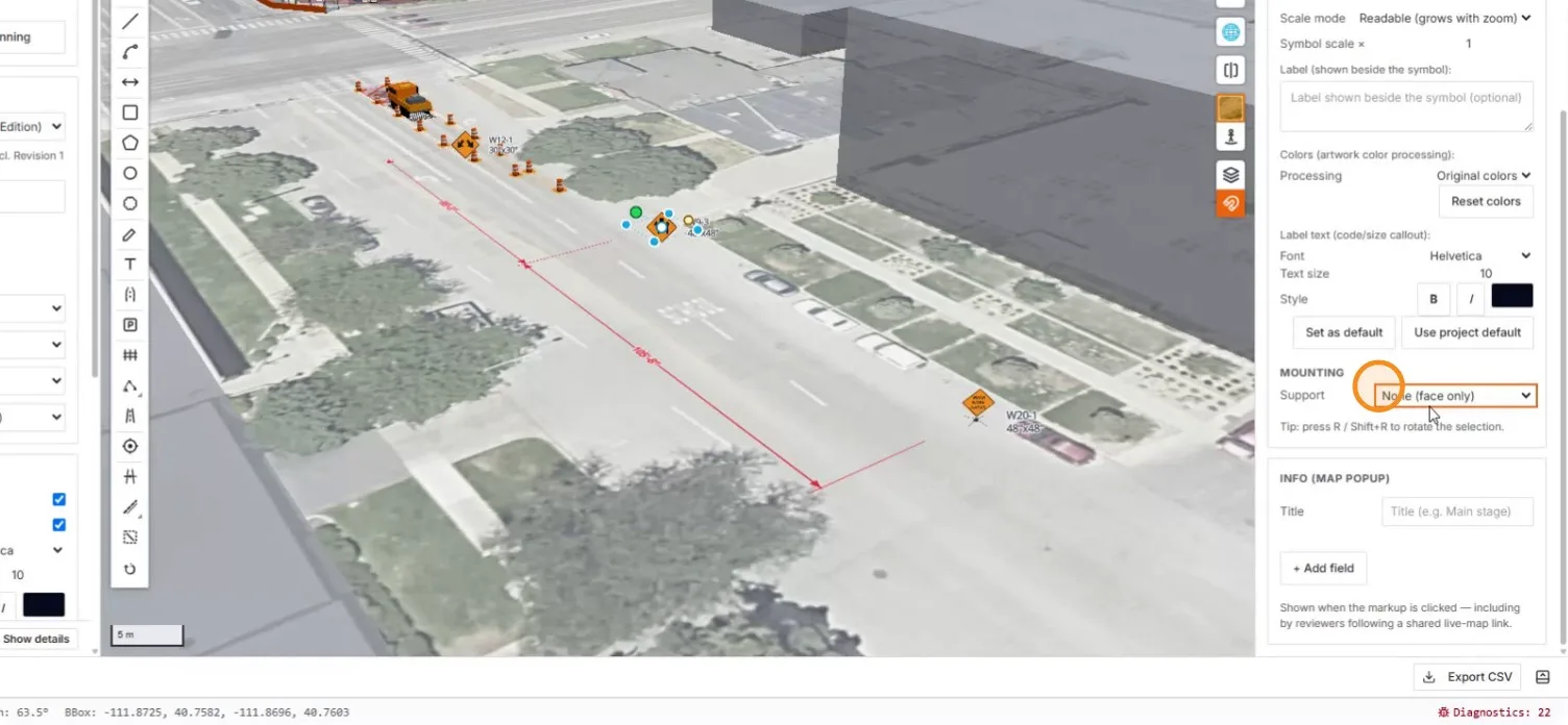
Look over the whole plan in 3D, then give each sign a support.
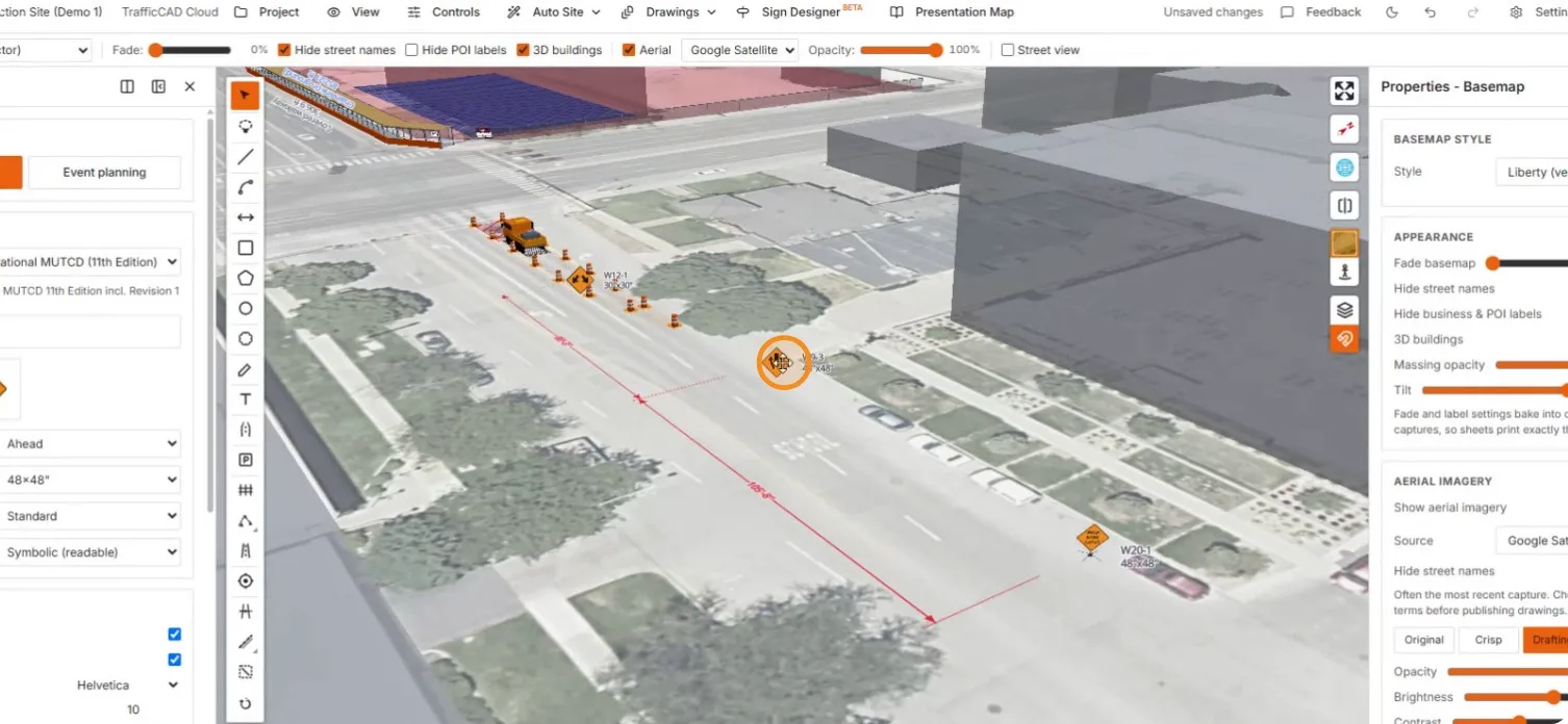
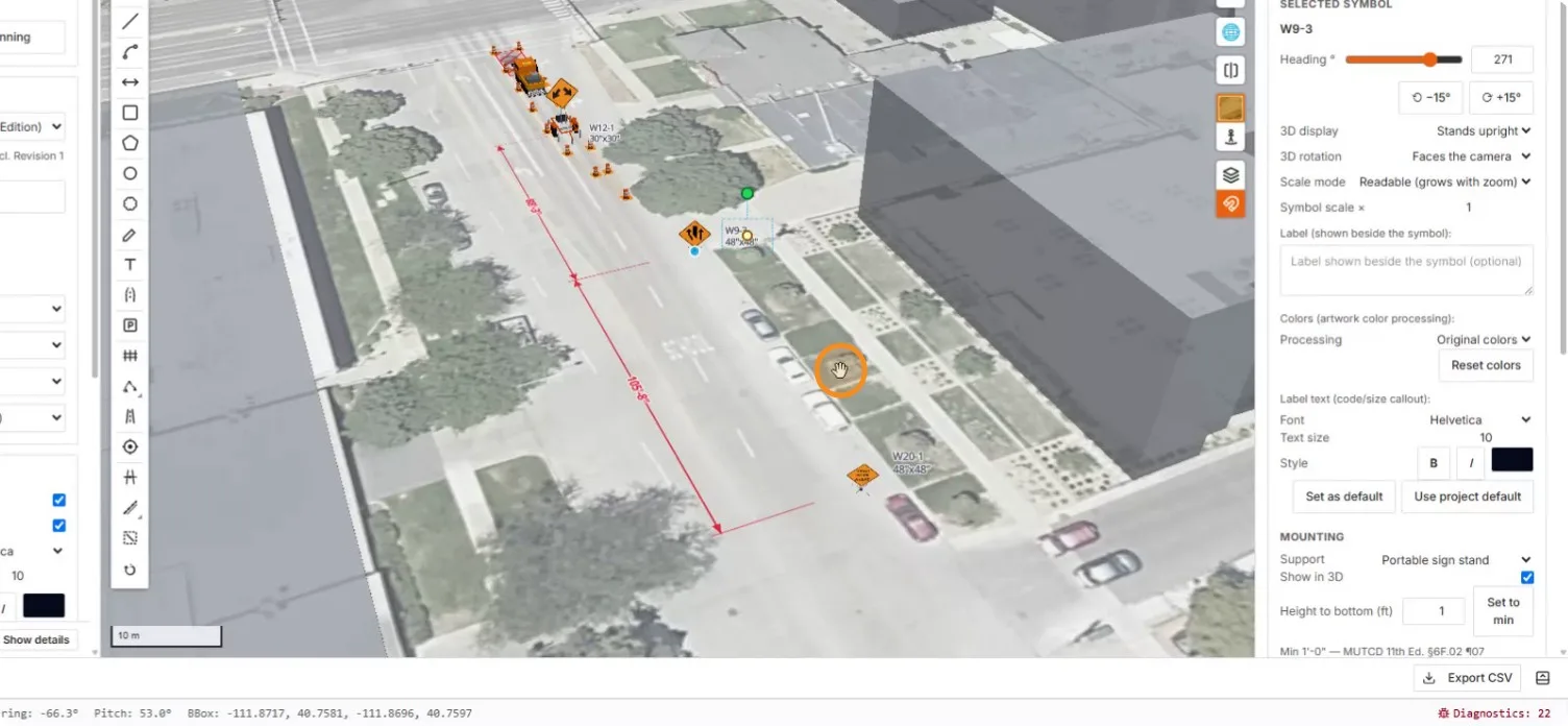
A tilted 3D overview — truck, drums, signs, dimensions, and 3D buildings

The W9-3 selected with its Mounting support set to None (face only)

The W12-1 selected in the 3D scene

Pick a support — here a portable sign stand. The mounting panel cites the MUTCD 6F.02 minimum height and confirms Heights comply.
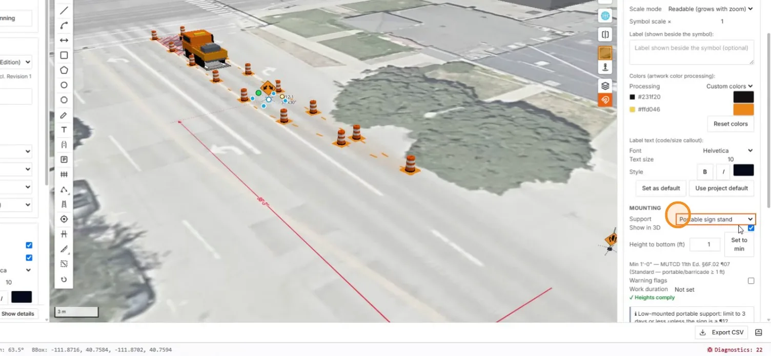
The W12-1 on a portable sign stand with the MUTCD height check passing

9. Control how signs face the camera

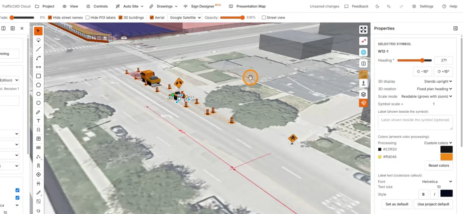
By default signs rotate to face the viewer. Disable that when a sign should hold its plan orientation.
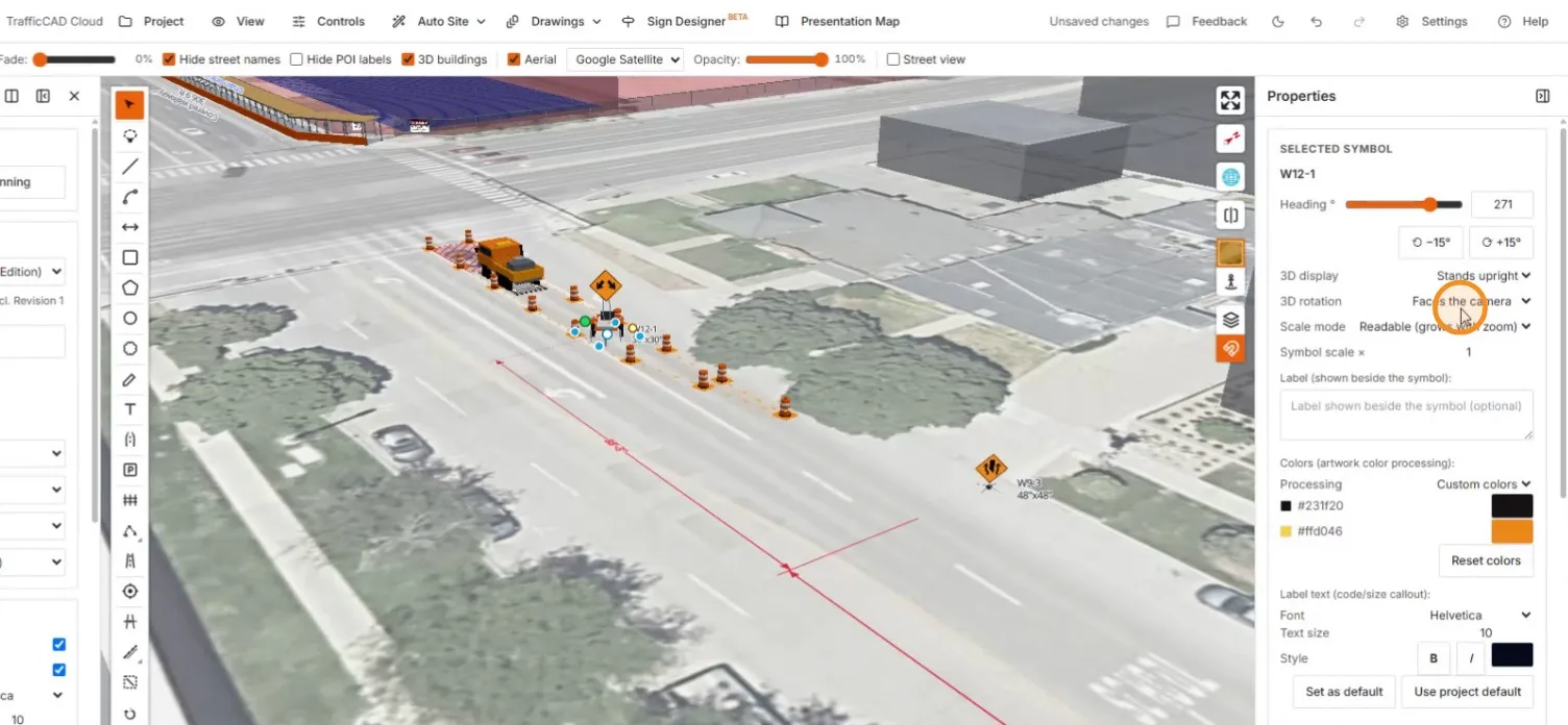
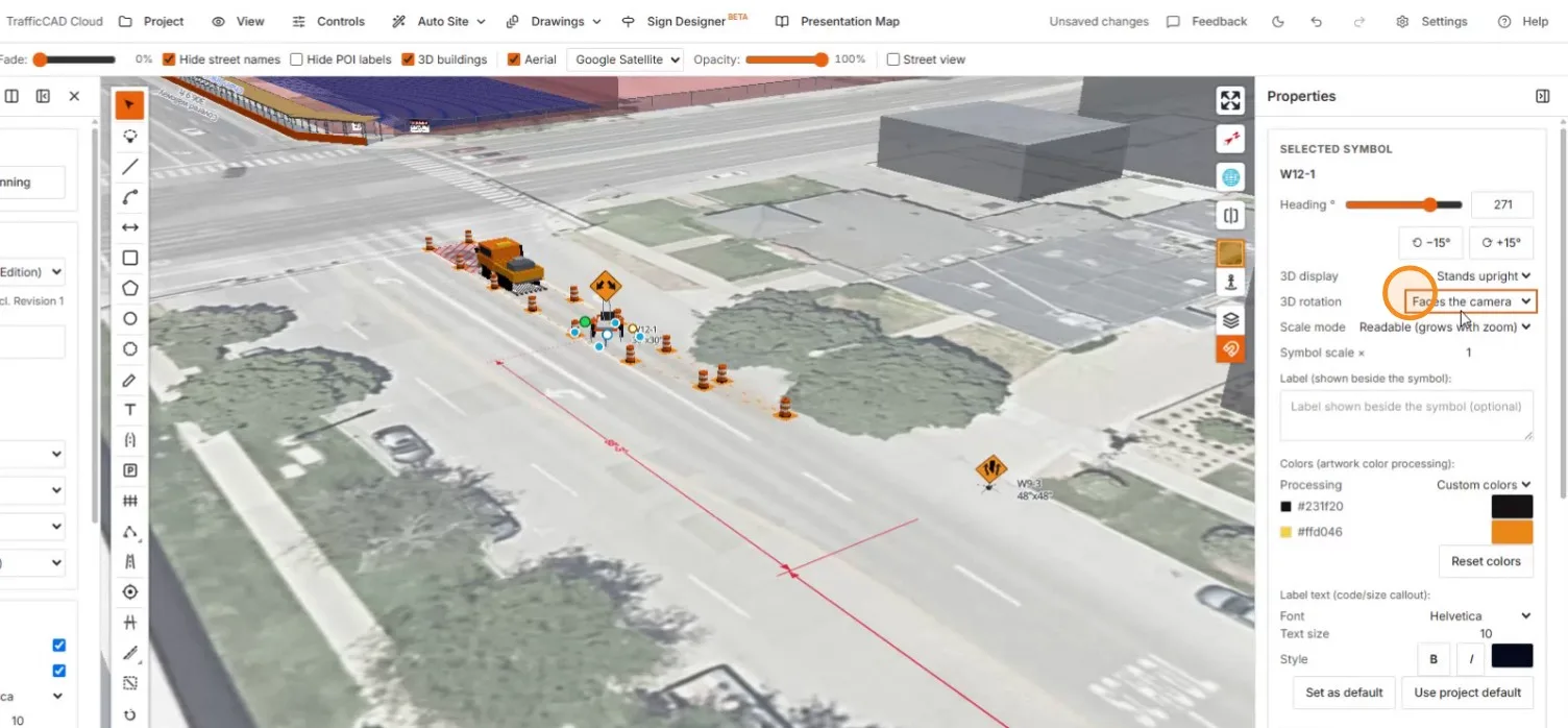
The 3D rotation dropdown reading Faces the camera

The same dropdown focused before switching modes

Fixed plan heading applied — the sign holds its orientation

10. Adjust scale and finalize

Scale the signs so the plan reads clearly at its output size, then review the final layout in plan and 3D.
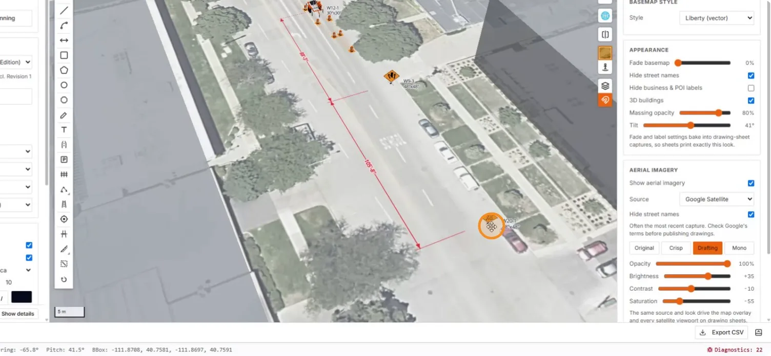
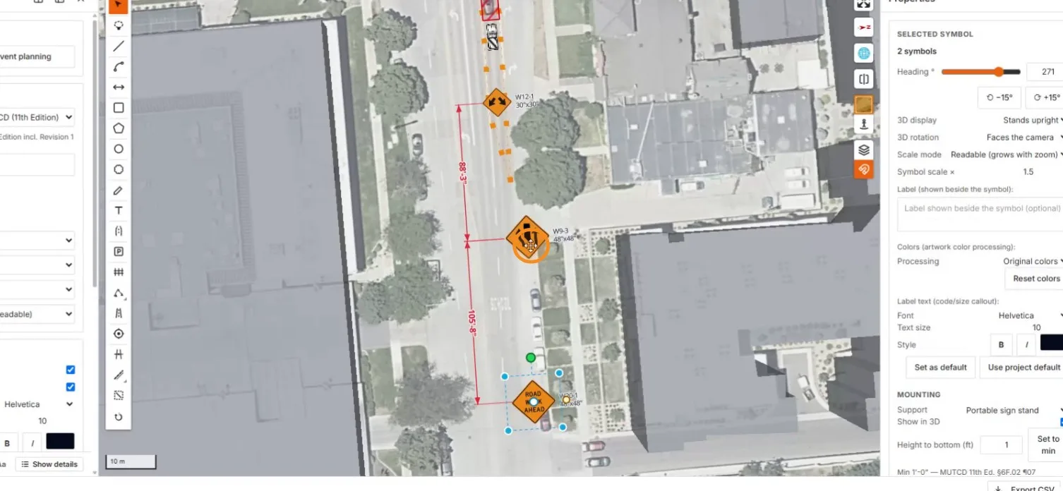
The dimensioned plan in a tilted view with all three signs

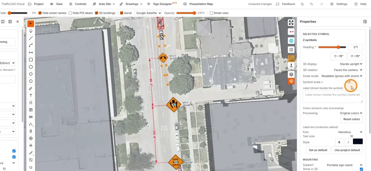
Two signs multi-selected and enlarged to symbol scale 1.5

The finished plan top-down: work area, truck, taper, signs, dimensions

The final tilted 3D review of the complete traffic control plan


Reference: Traffic Control Plans (MUTCD) · Channelizing Devices · Sign Display, Labels & Leaders · Dimensions & Callouts

Next steps: Create Drawings — put this plan on a titled sheet with schedules and details.