Skip to content

Create Drawings

Compose a full drawing set inside TrafficCAD: viewports with live scales, title blocks, captured 3D views, sign schedules and MUTCD tables, PDF markups, and a fully editable typical application on its own sheet. About ten minutes.

The recording this tutorial follows (9:51).

1. Open the Drawings tool

Click Drawings in the top toolbar to open the drawing creator.
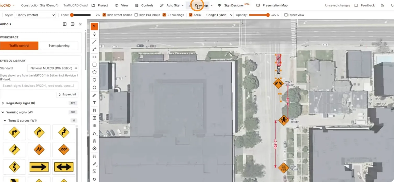
The map workspace with the Drawings button under the cursor

2. Add a viewport

A new sheet starts with a title block and nothing else. Add a Viewport and frame the model content it should show.
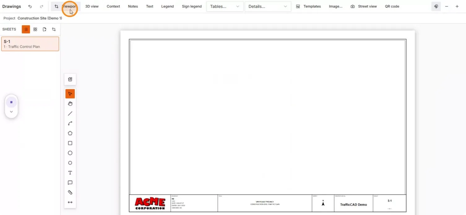
A blank S-1 Traffic Control Plan sheet with the Viewport button

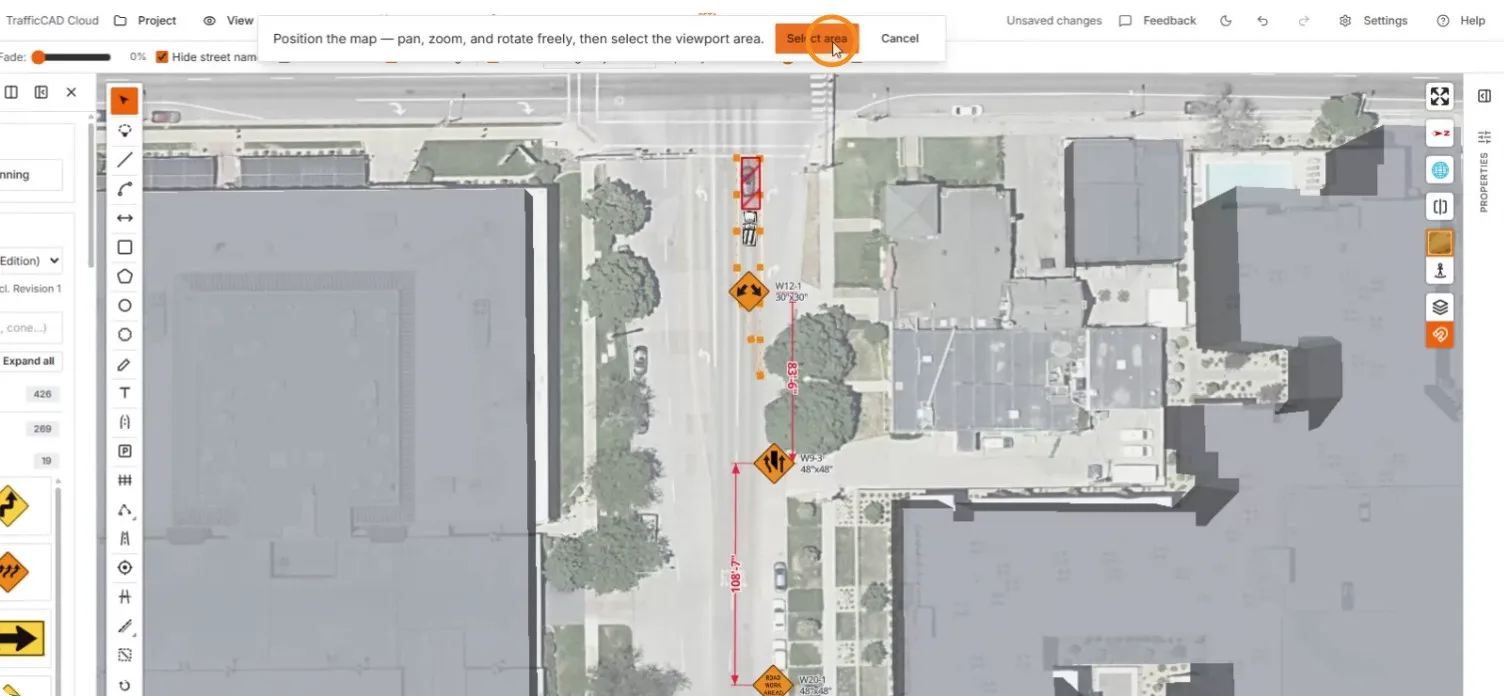
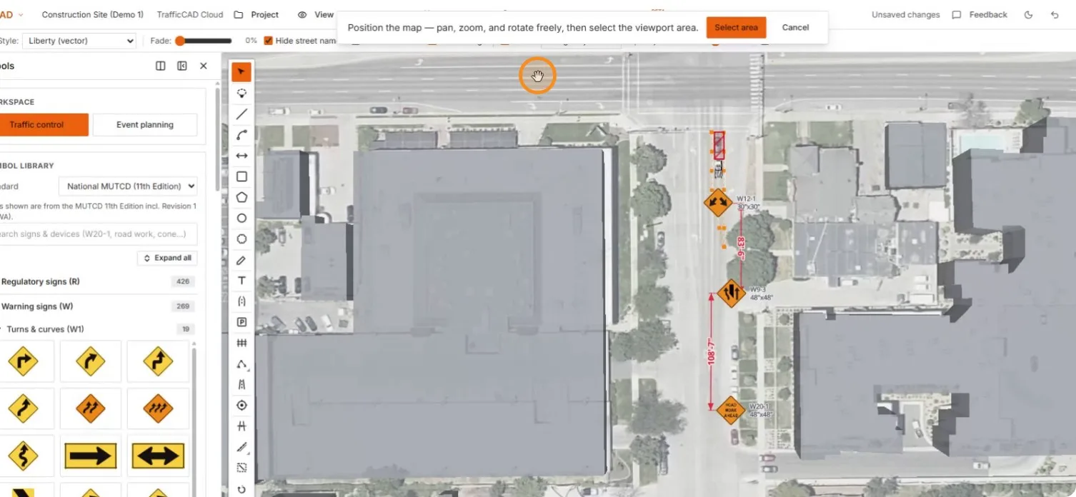
Viewport-capture mode: position the map, then select the area

The corridor framed, cursor on the Select area button

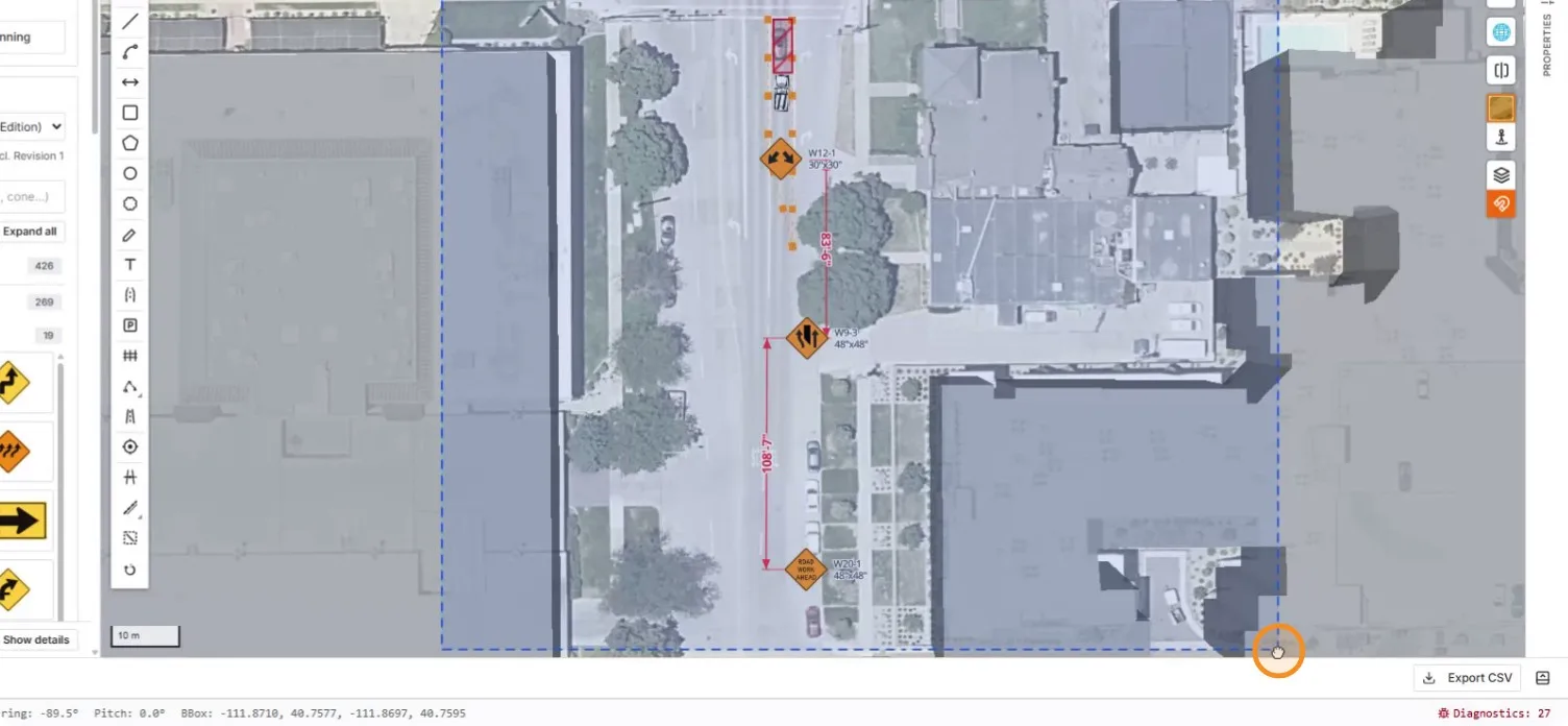
Dragging the blue detail box around the signed corridor

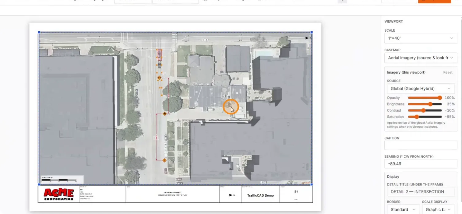
The generated viewport with its properties: scale, imagery source, detail title

3. Position and scale the viewport

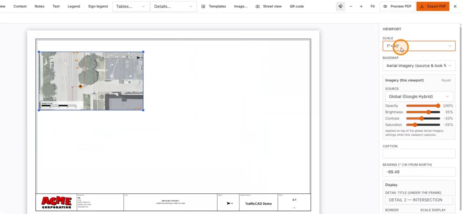
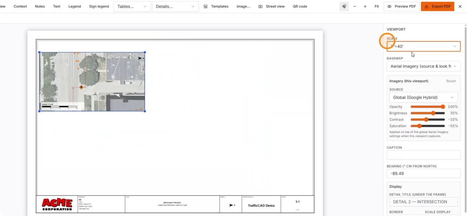
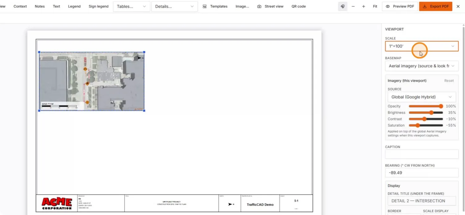
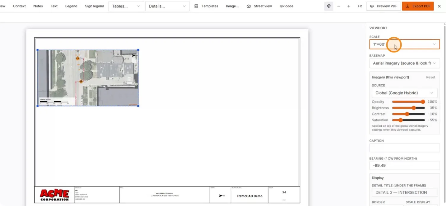
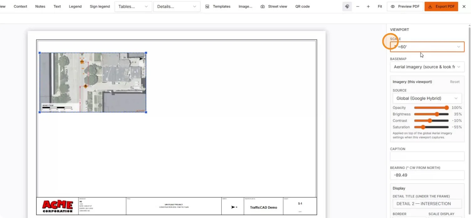
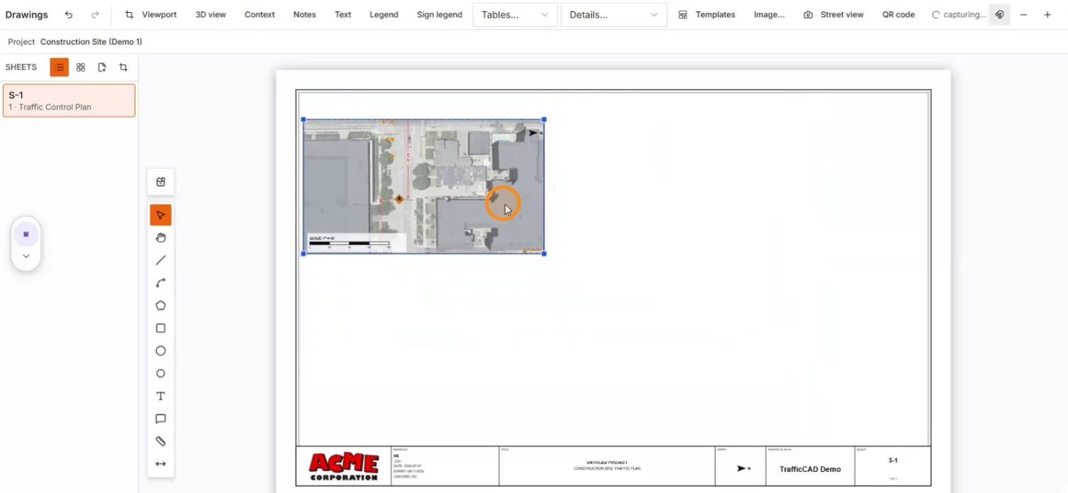
Drag the viewport into place, then work the Scale dropdown — the drawing re-renders to the new scale each time.
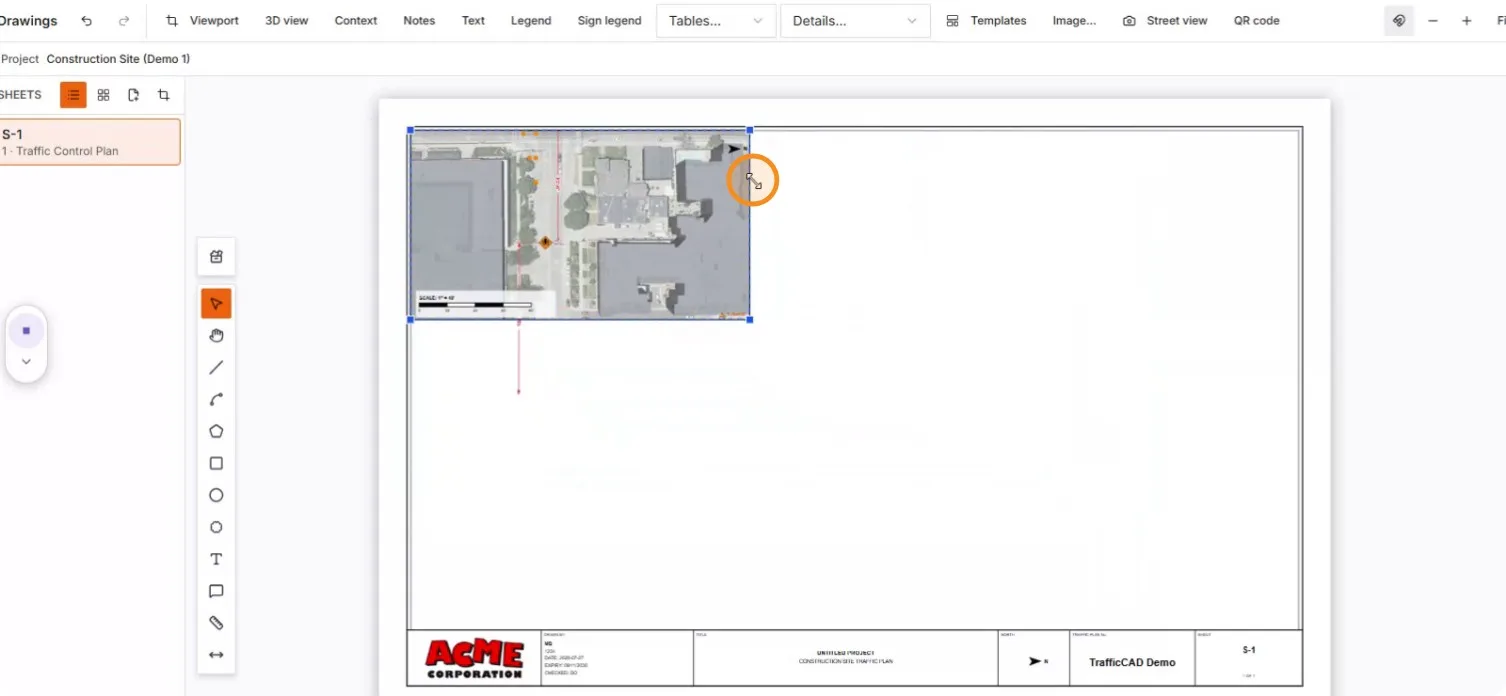
The viewport dragged toward the sheet's top-left

The viewport recapturing imagery as it settles

The Scale dropdown reading 1 inch = 40 ft

The scale field focused before the change

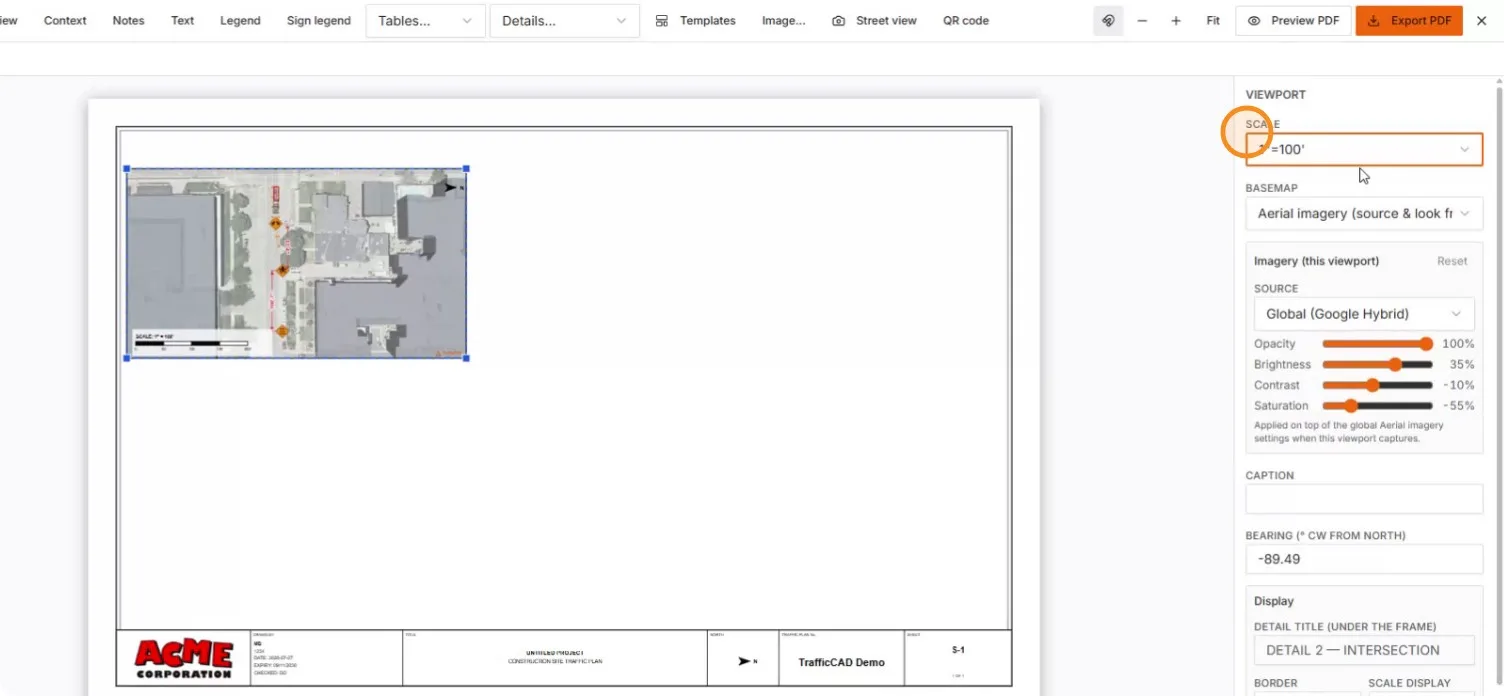
At 1 inch = 100 ft the same frame covers a wider area

The 1 inch = 100 ft state

Trying 1 inch = 60 ft

The 1 inch = 60 ft state confirmed

Resize the frame itself when the sheet composition needs it.
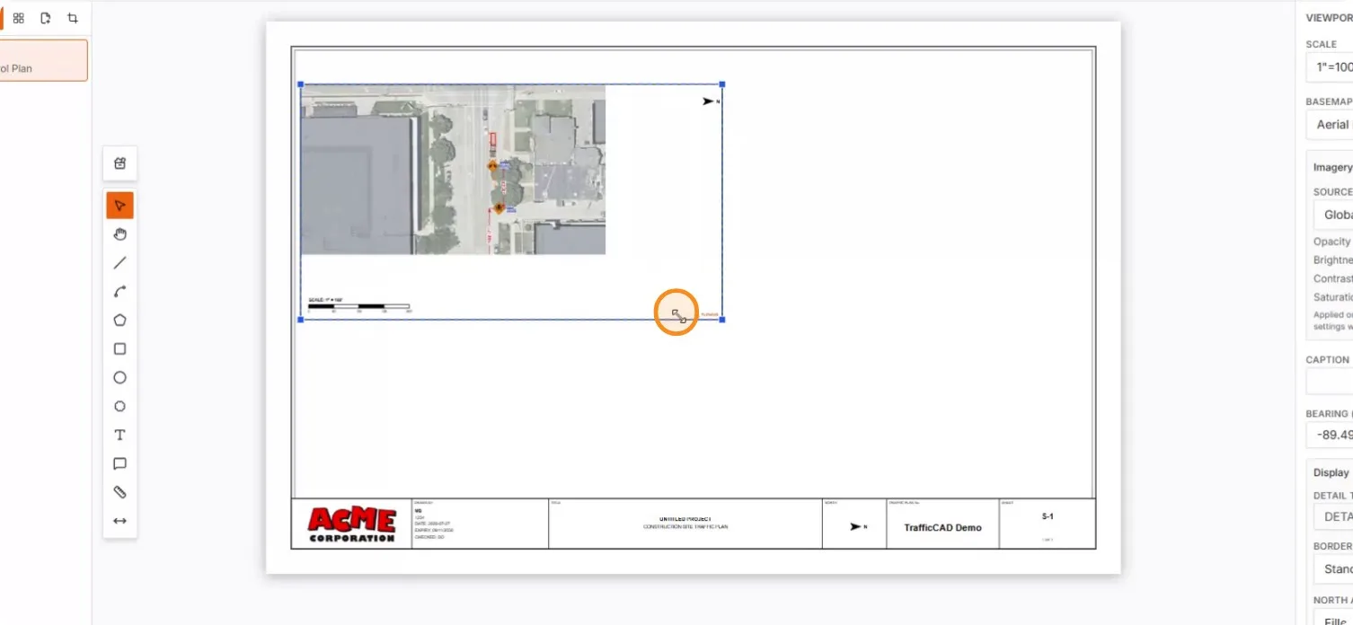
The frame stretched, imagery re-capturing to fill it

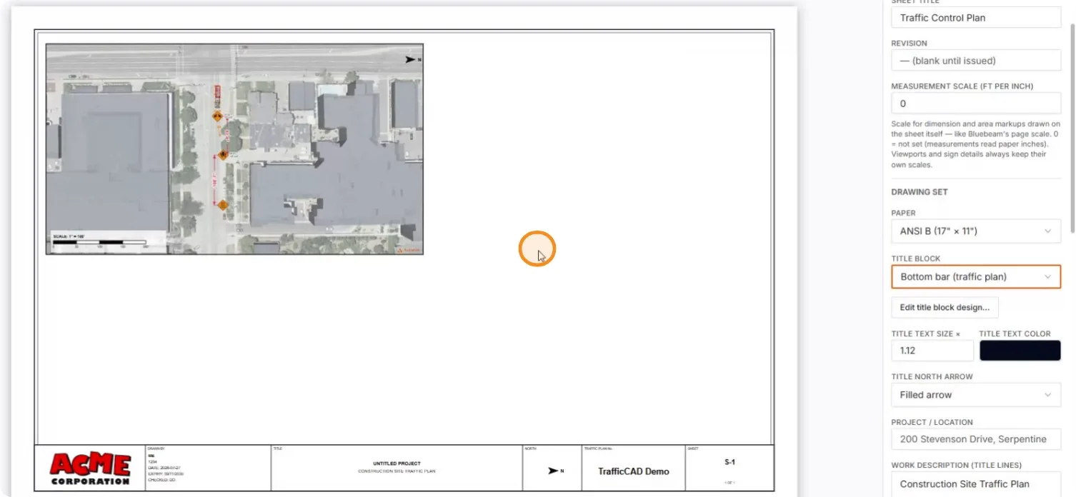
The resized viewport spanning the upper half of the sheet

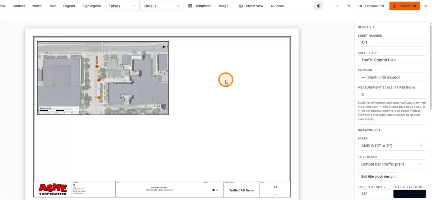
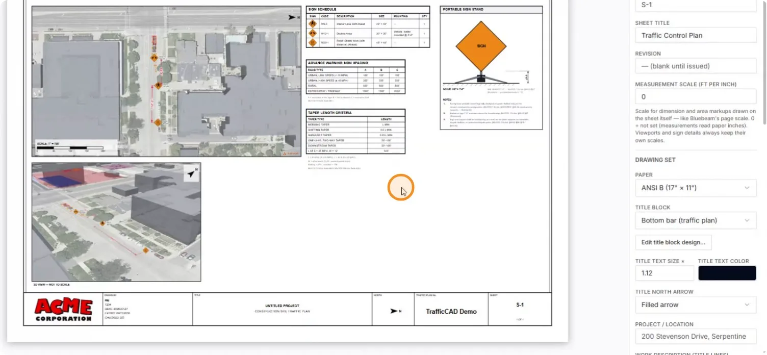
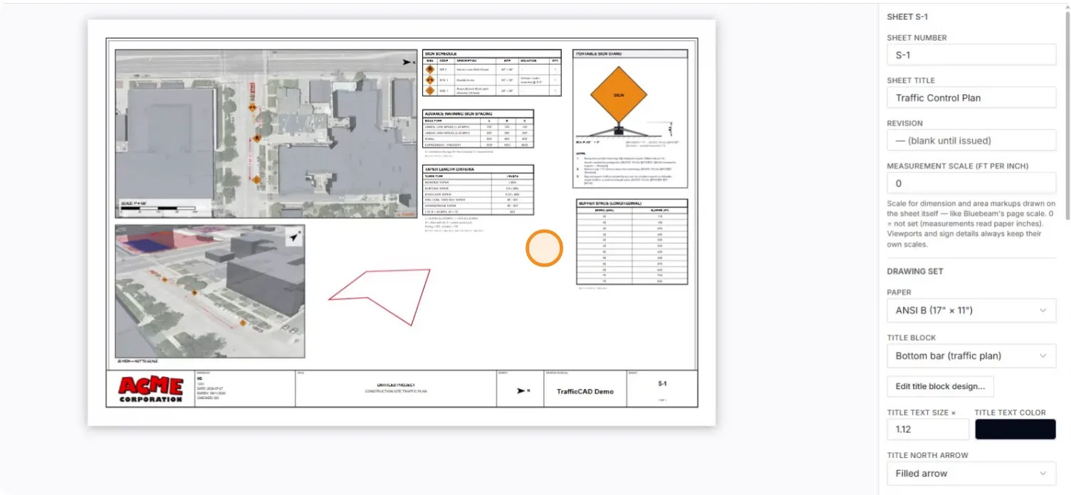
The Sheet S-1 properties: number, title, revision, paper size

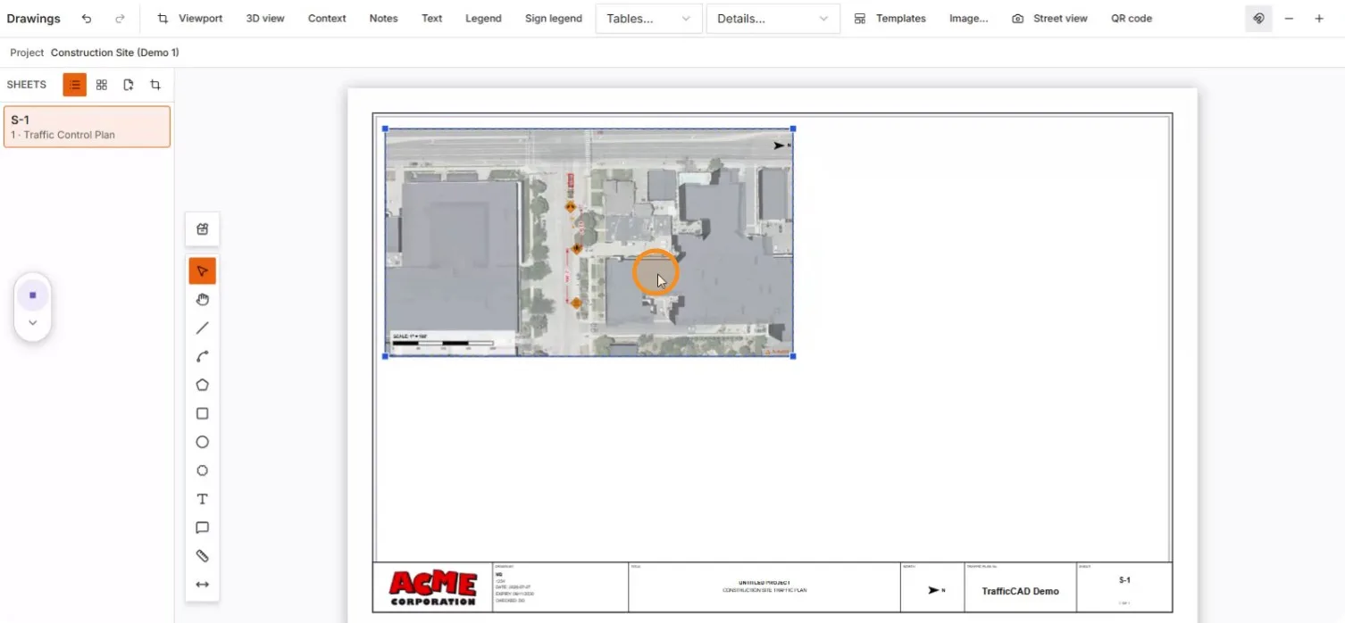
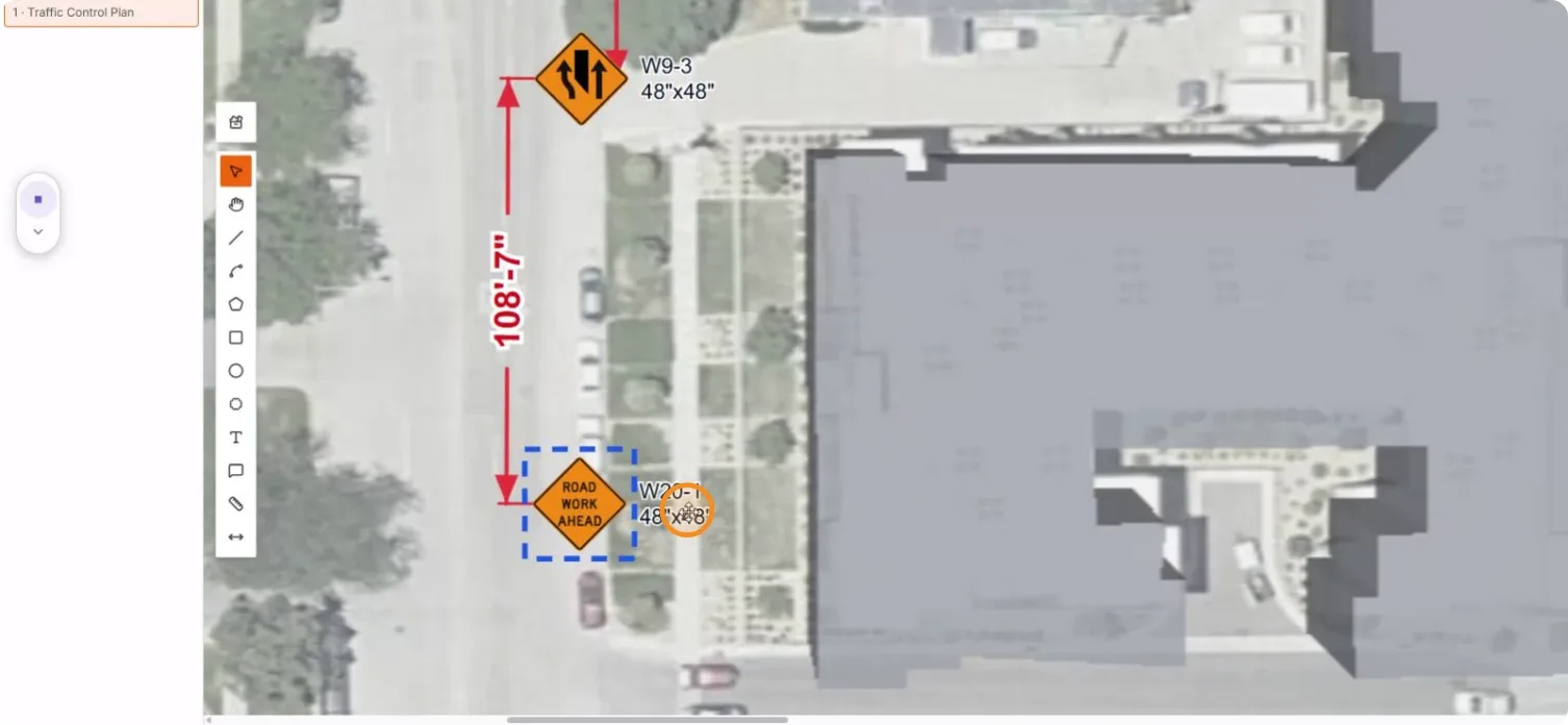
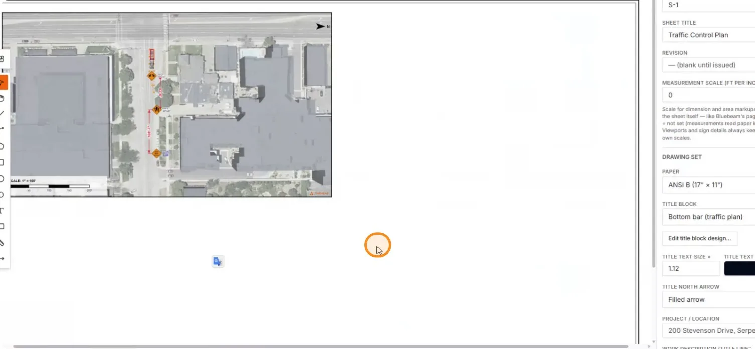
Elements inside the viewport stay live — grab a sign on the sheet and move it.
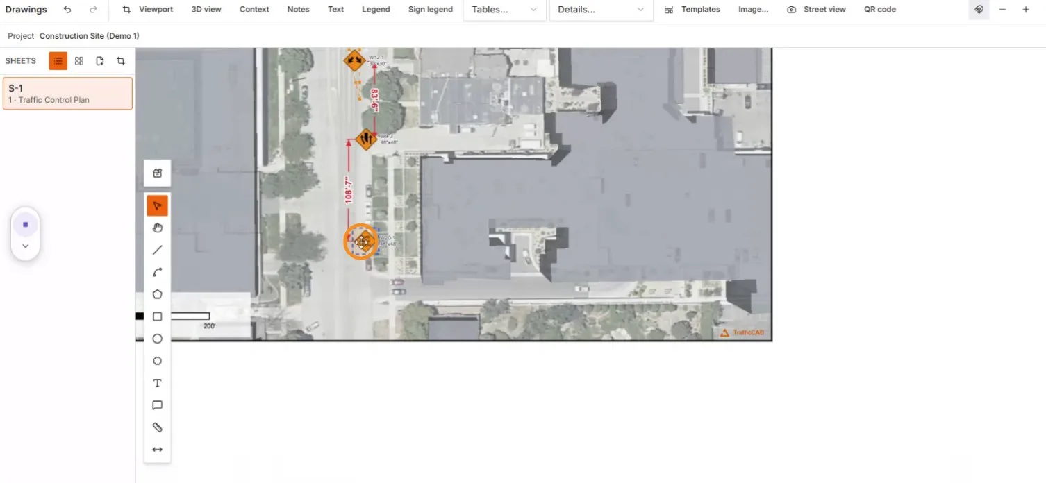
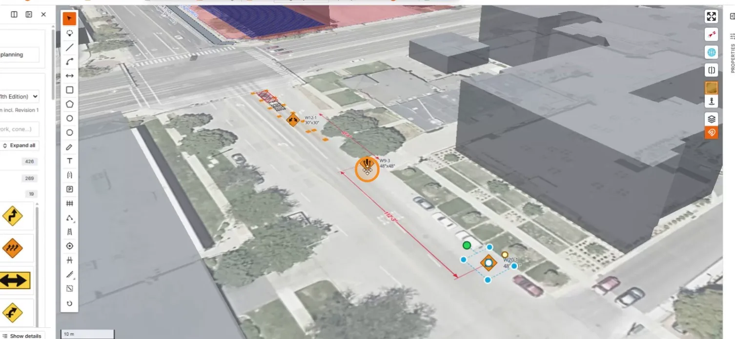
Zoomed into the sheet, grabbing the W20-1 sign

The ROAD WORK AHEAD sign selected on the sheet imagery

The sheet properties scrolled to title block and project fields

4. Choose a title block

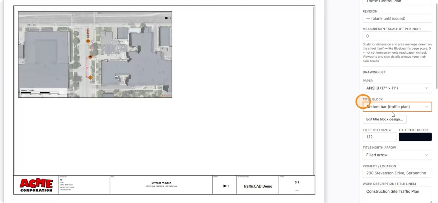
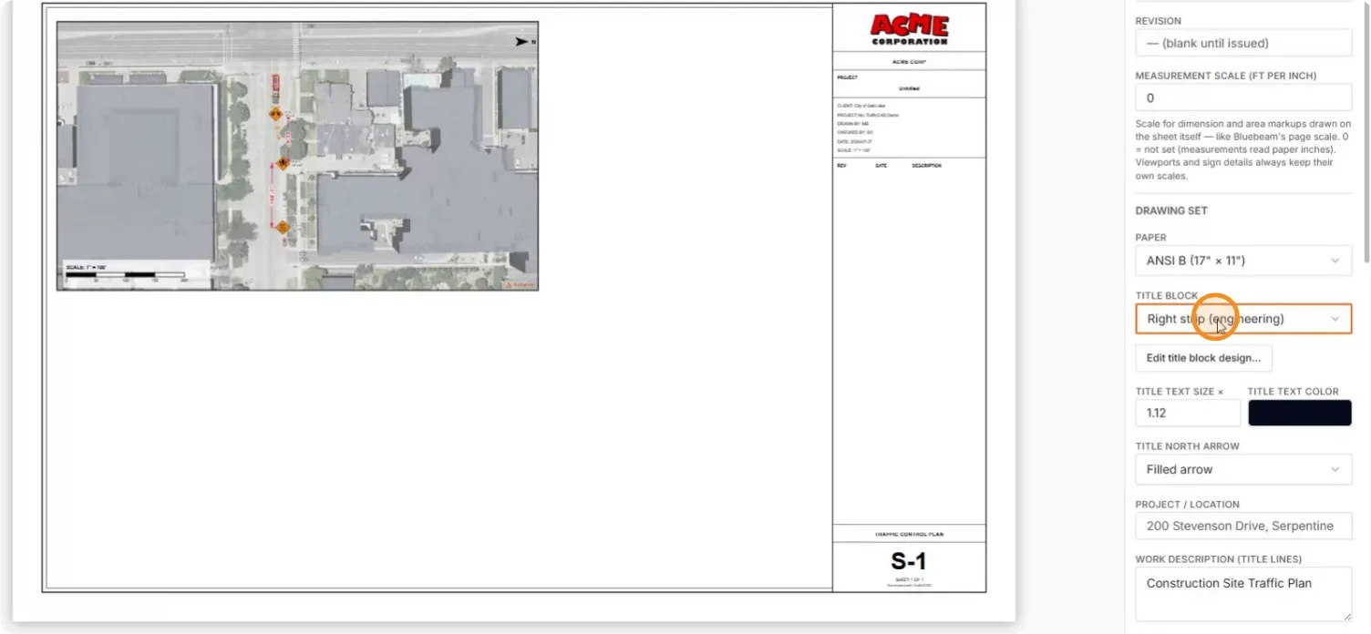
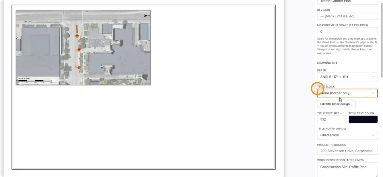
Title blocks are templates — switch styles and the sheet re-renders.
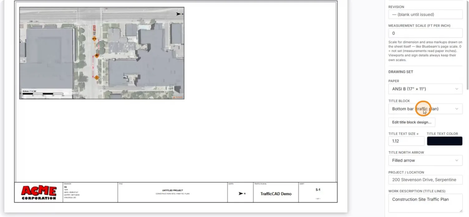
The Title Block dropdown reading Bottom bar (traffic plan)

The dropdown focused to browse options

The Right strip (engineering) title block applied

The None (border only) option

Bottom bar re-selected as the final choice

5. Add a 3D view

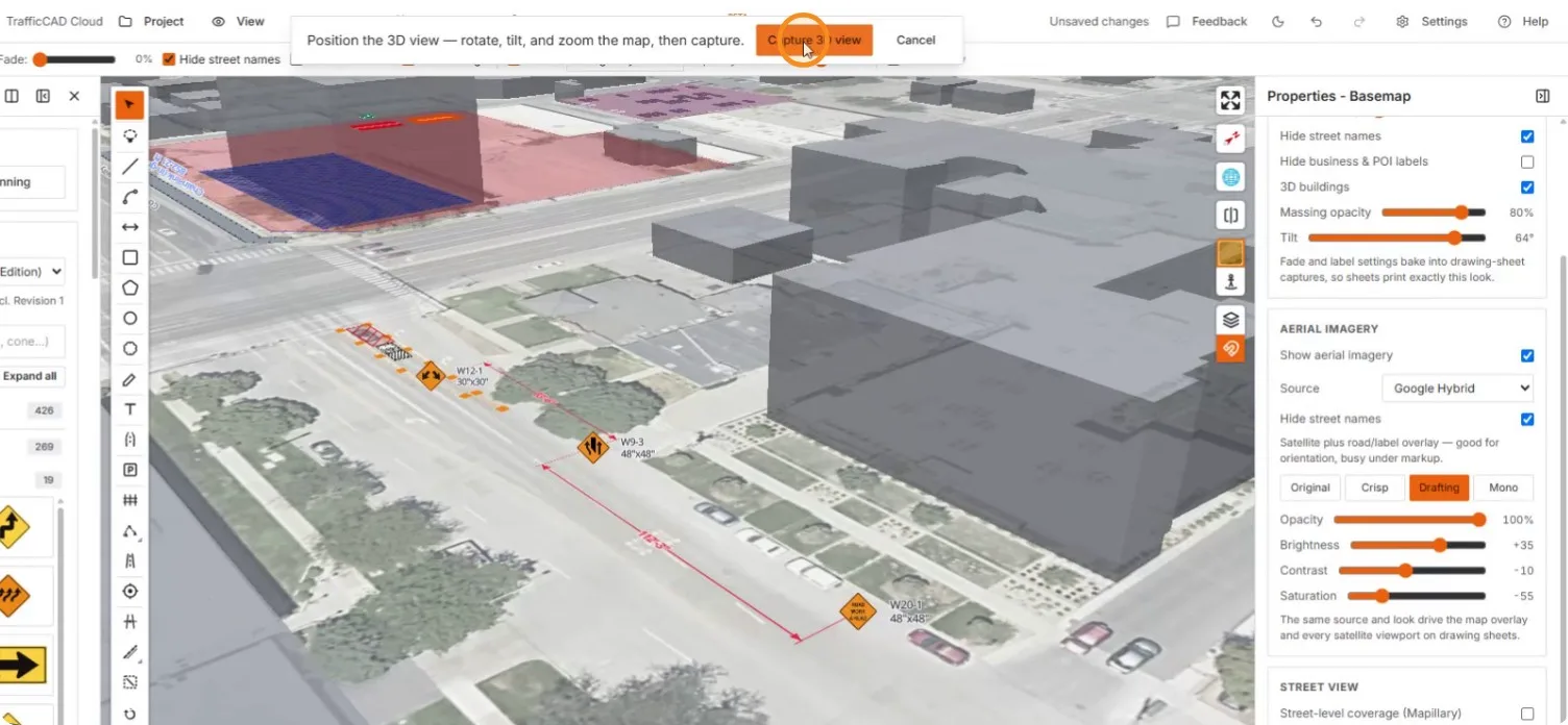
Click 3D view, frame the model in 3D, and capture it onto the sheet.
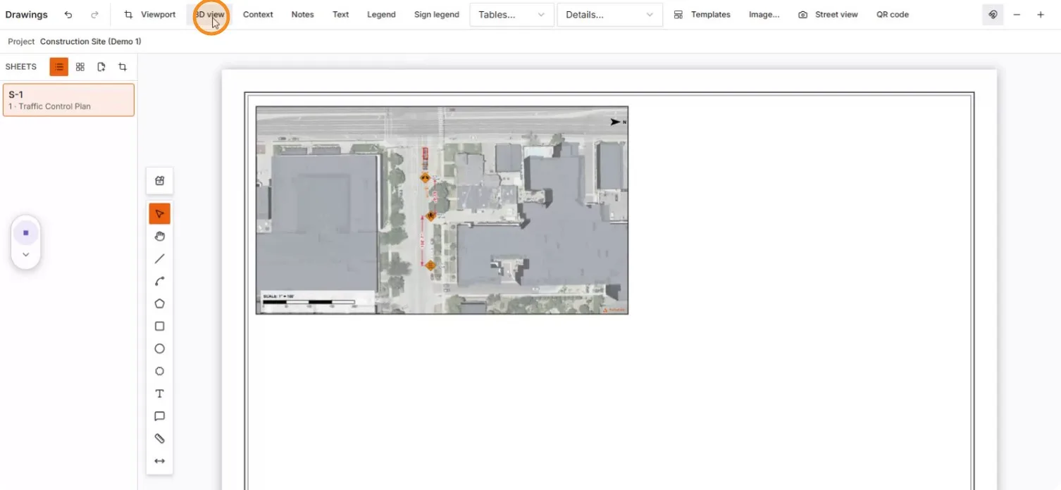
The 3D view button in the drawings toolbar

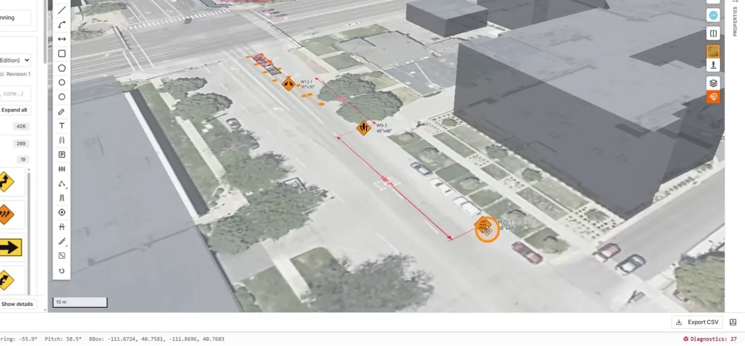
The tilted 3D corridor with the sign chain along the red dimension

Framing signs in 3D — the W20-1 selected

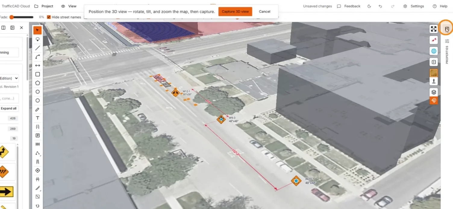
The capture banner: rotate, tilt, zoom, then capture

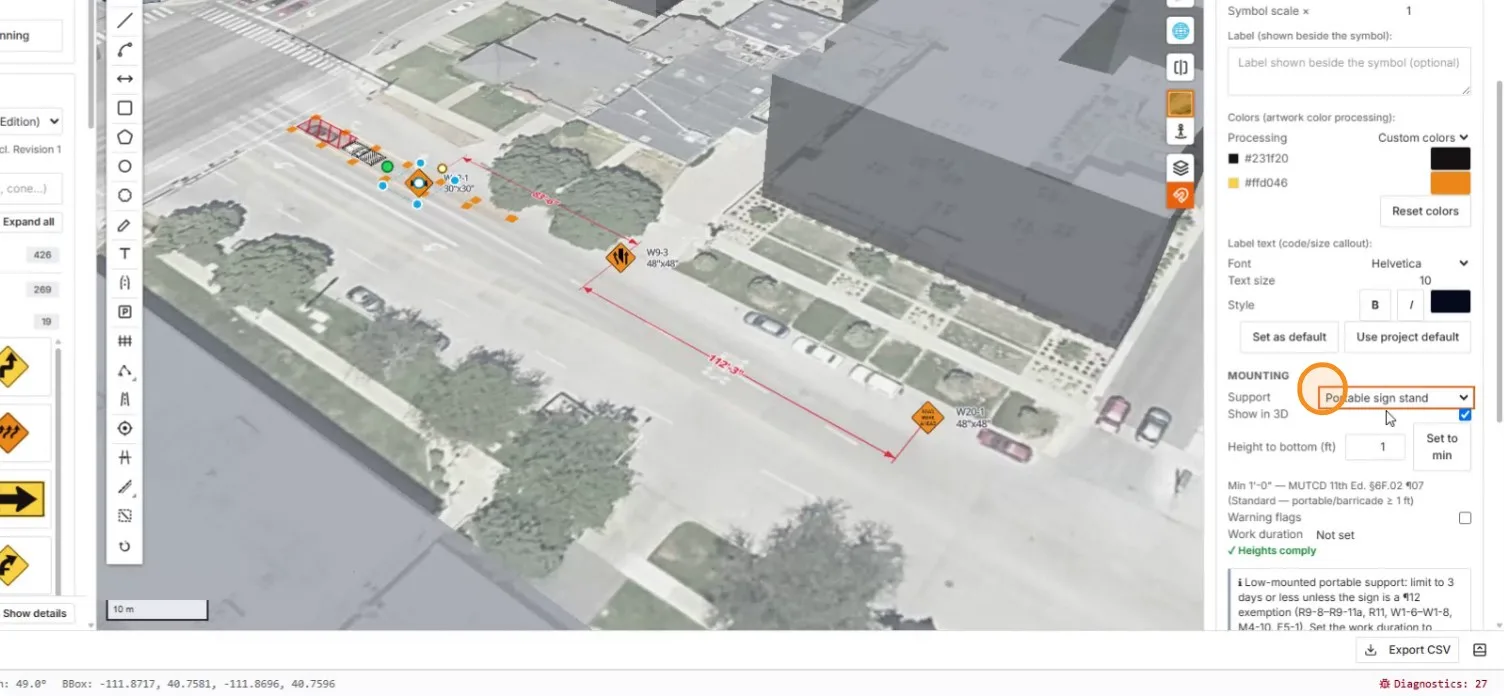
A sign's mounting properties with the MUTCD 6F.02 height check

The framed view ready, Capture 3D view under the cursor

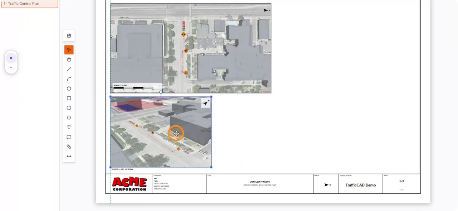
The captured 3D view dragged into place on the sheet

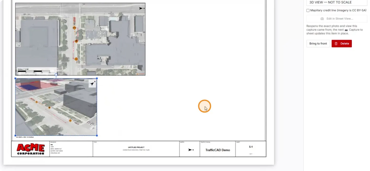
The 3D view item's properties: caption and ordering

6. Insert and format tables

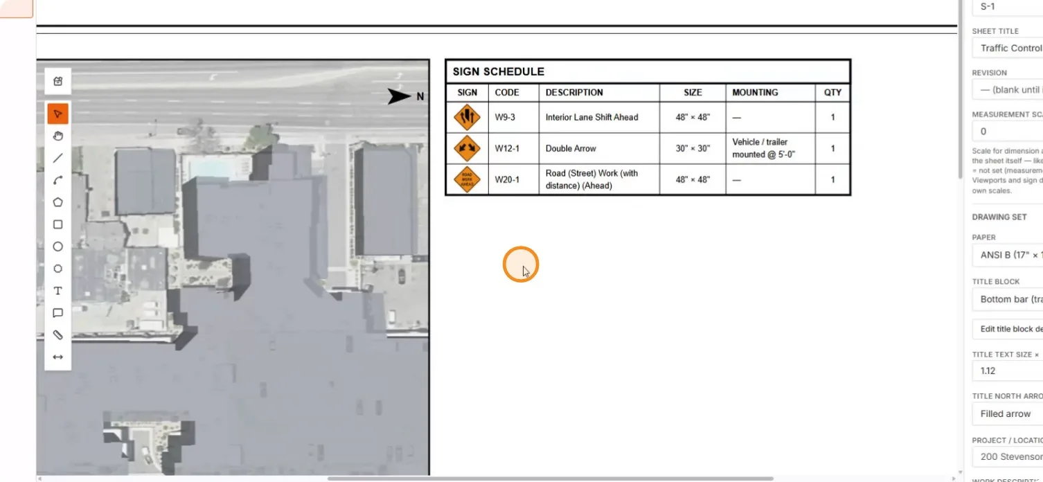
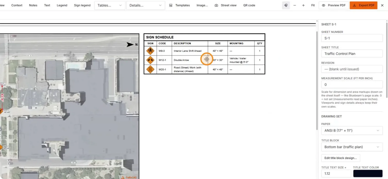
Add a sign schedule — it reads the plan and lists every sign with code, size, mounting, and quantity.
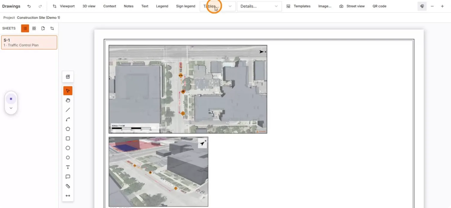
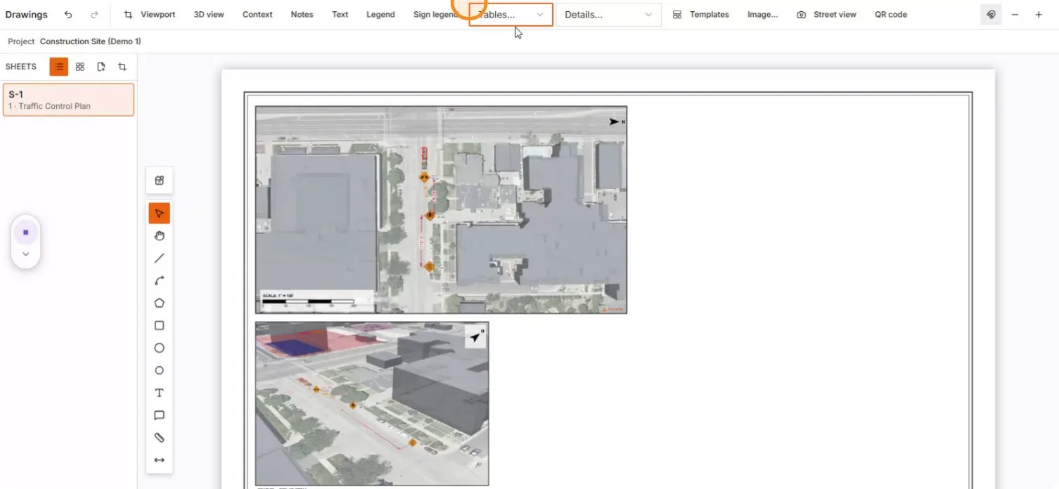
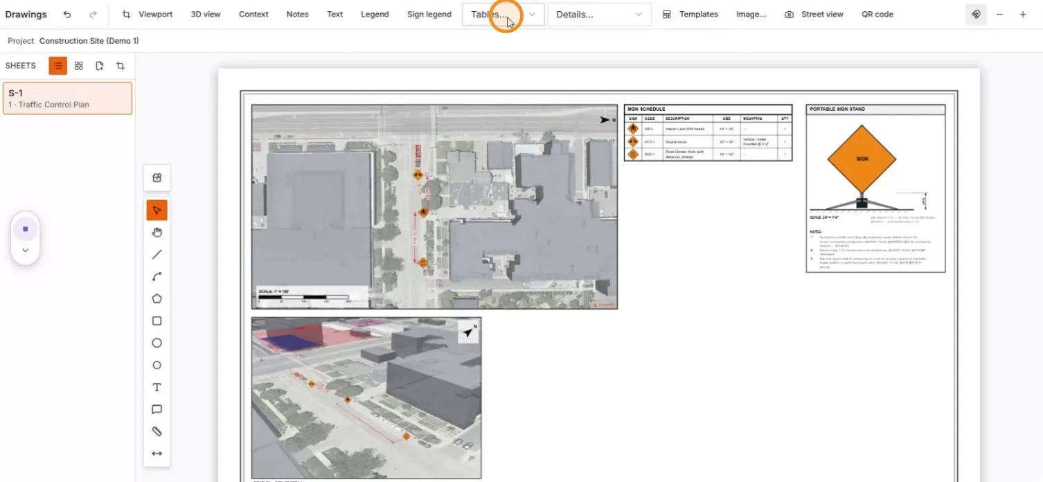
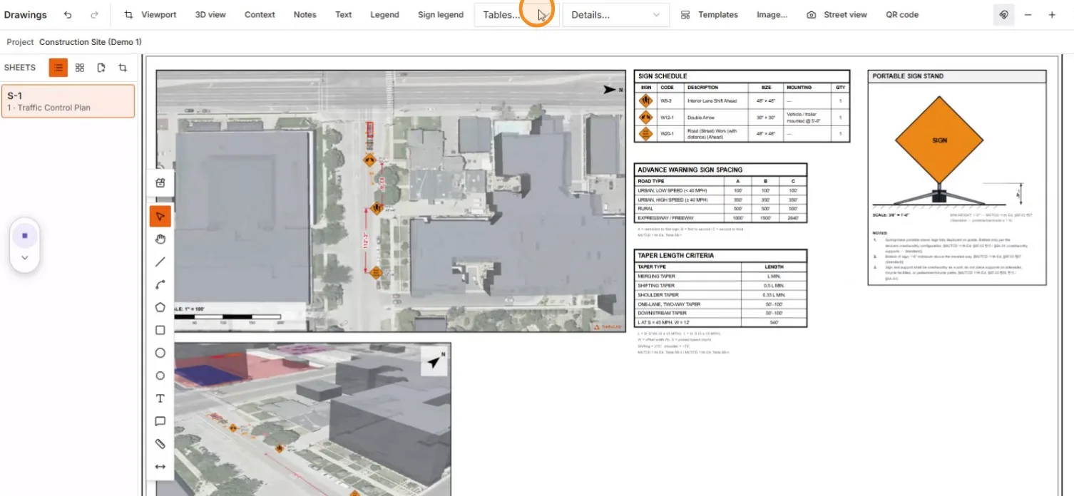
The Tables dropdown in the toolbar over the composed sheet

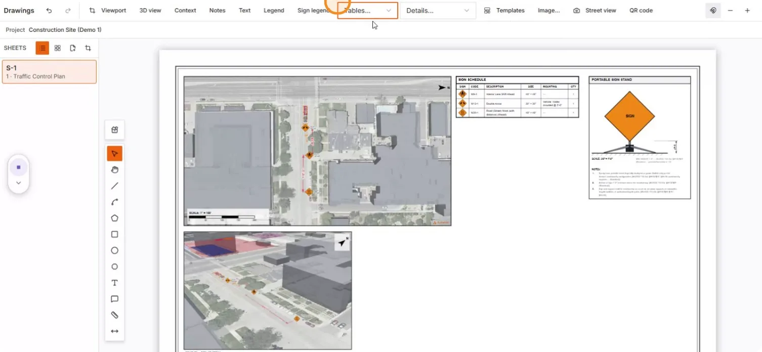
The Tables dropdown focused

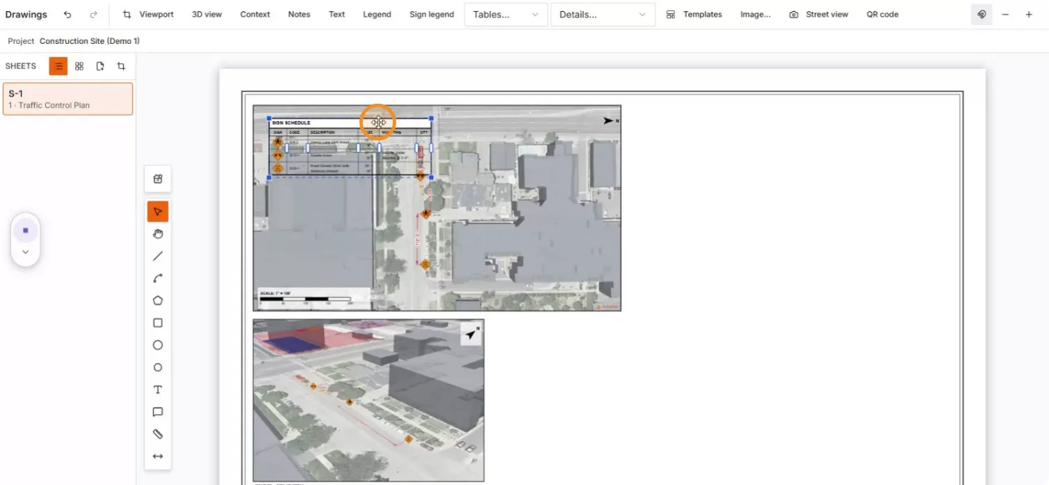
The inserted sign schedule dropped over the viewport

The schedule dragged into clear sheet space

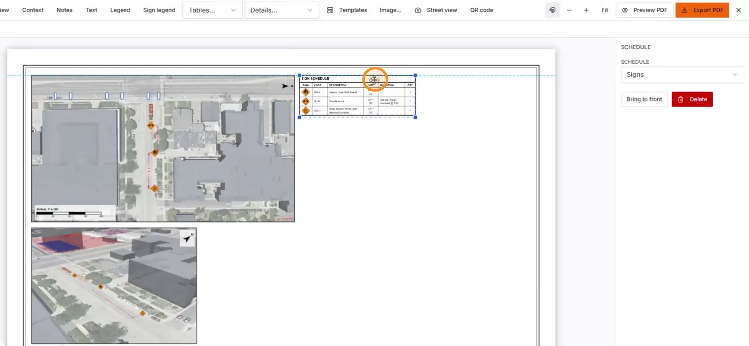
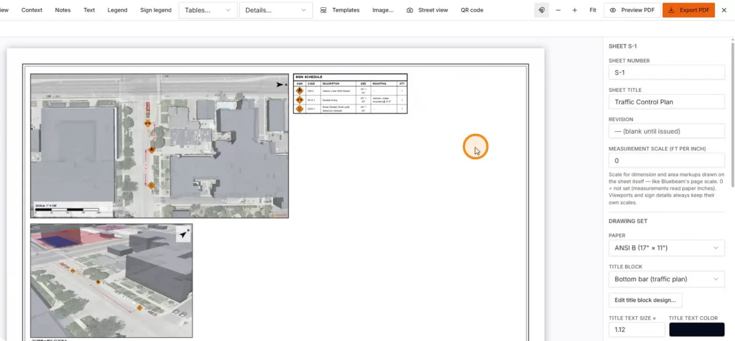
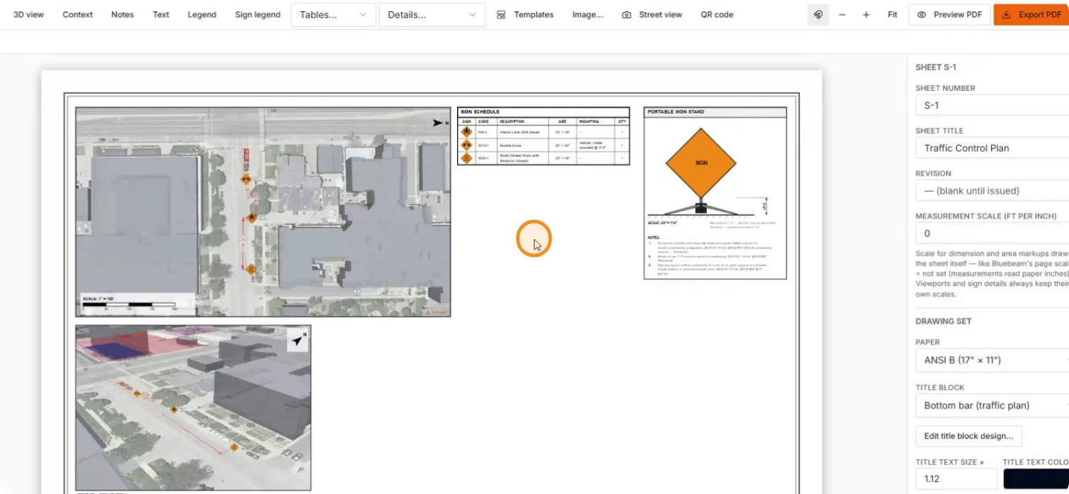
Plan viewport, 3D view, and sign schedule composed on the sheet

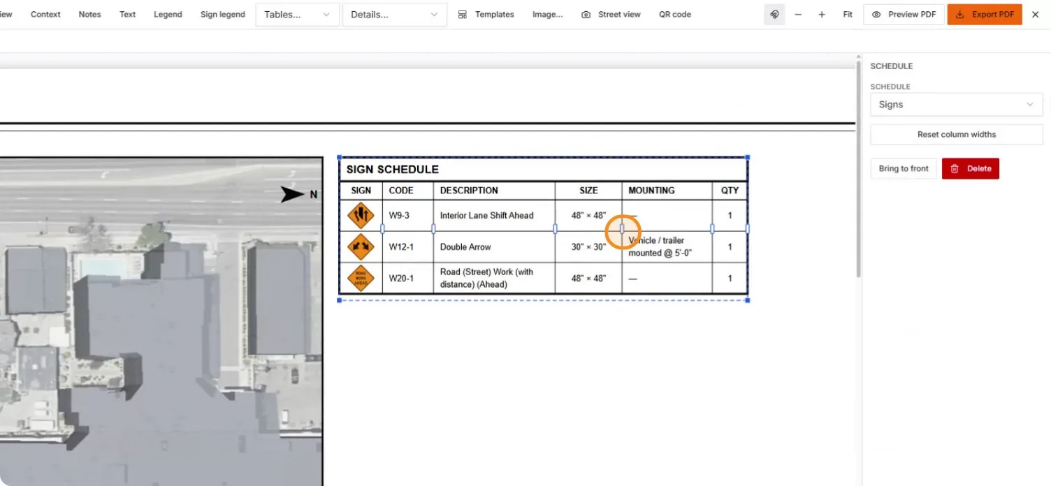
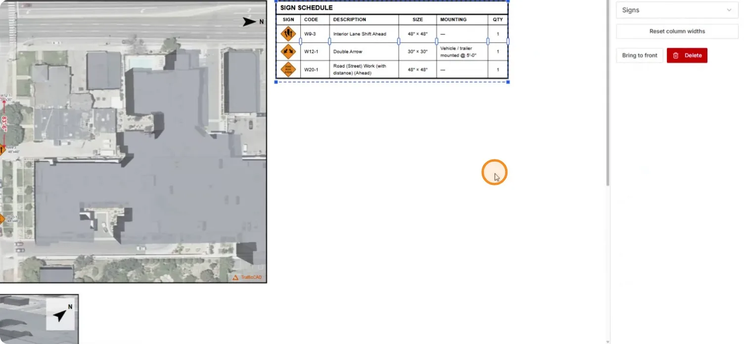
The schedule's rows — W9-3, W12-1, W20-1 — with resizable columns

The schedule beside the plan viewport

Repositioning the table on the sheet

The table selected with its column handles

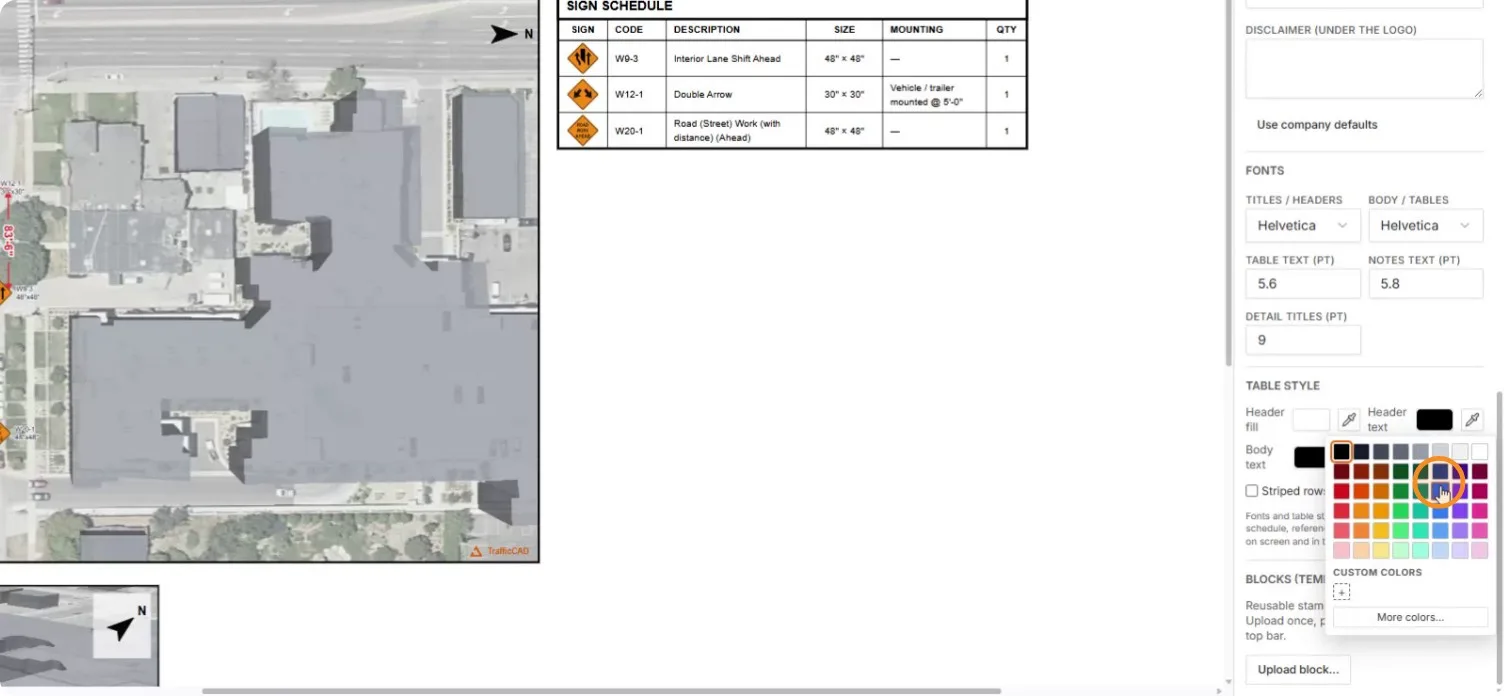
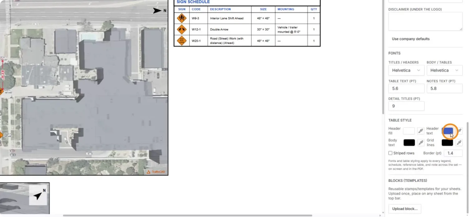
Table styling is per-sheet: fonts, header colors, grid lines, striping.
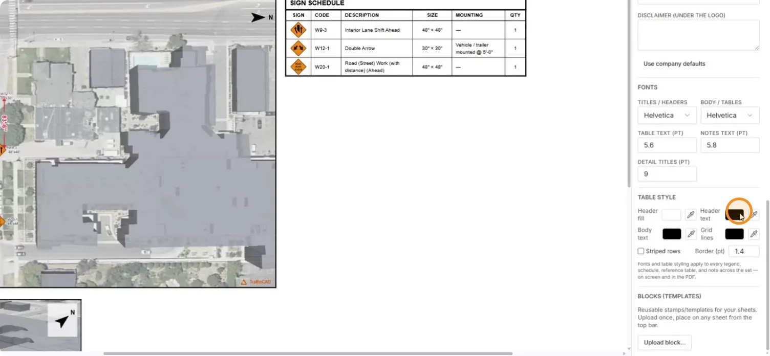
The Table Style controls with the header text swatch

The header color palette open

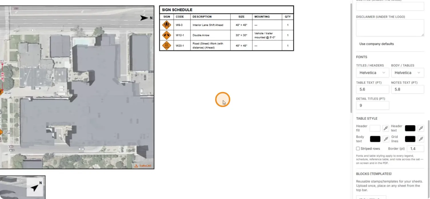
The schedule re-rendered with blue headers

Headers reverted to black

7. Add details and MUTCD tables

Details and the MUTCD reference tables drop in the same way.
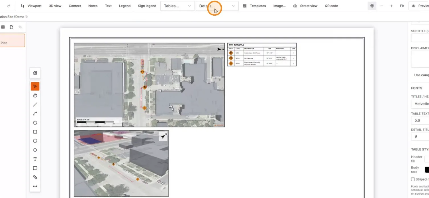
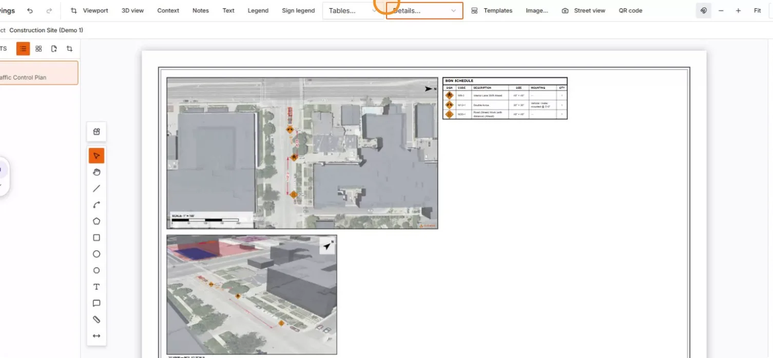
The Details dropdown in the toolbar

The Details dropdown highlighted

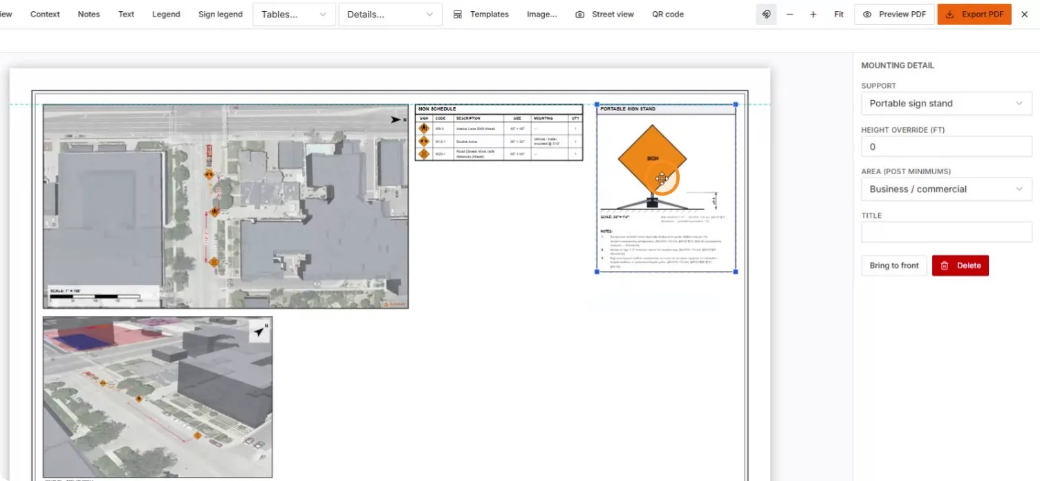
The portable sign stand mounting detail placed and selected

The sheet with viewport, 3D view, schedule, and mounting detail

Back to the Tables dropdown for the MUTCD tables

The Tables dropdown highlighted again

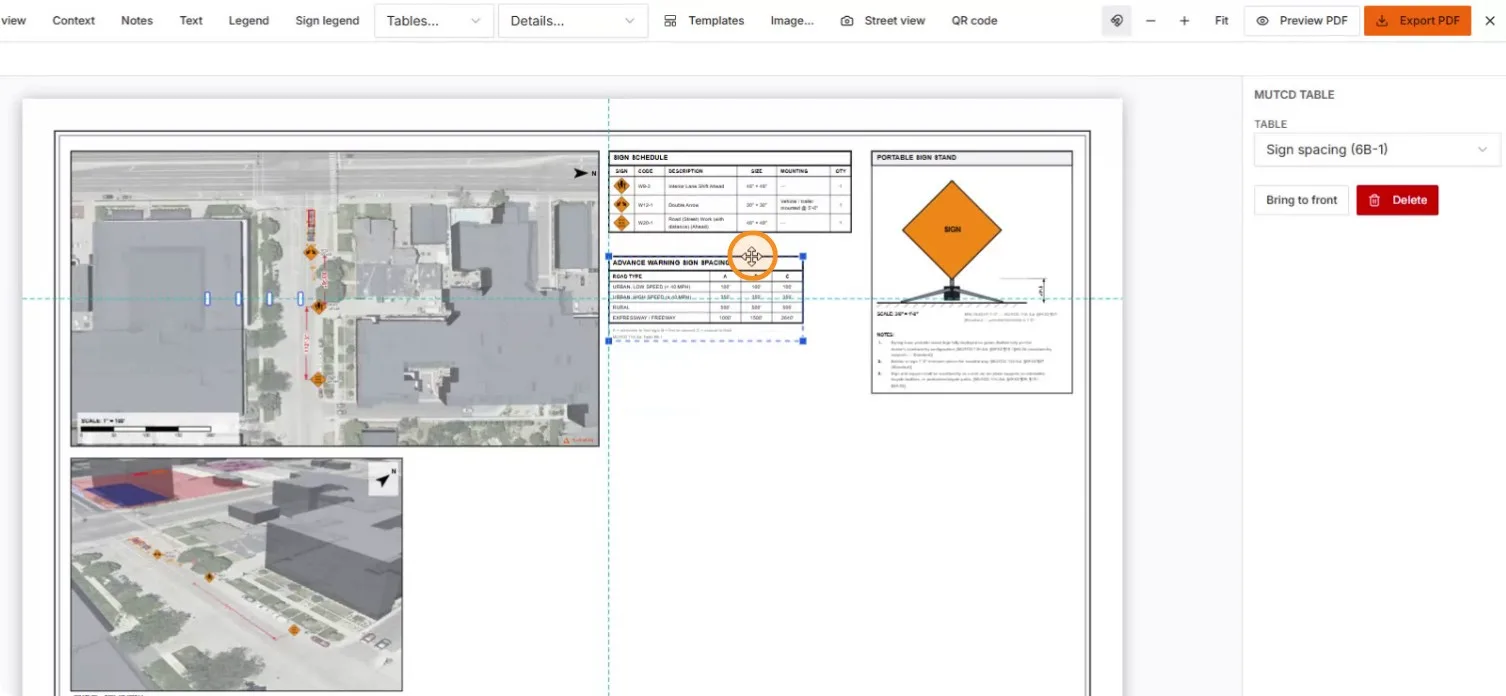
The Advance Warning Sign Spacing (6B-1) table snapping into place

Sign spacing and Taper Length Criteria tables placed

The sheet carrying the full MUTCD table set

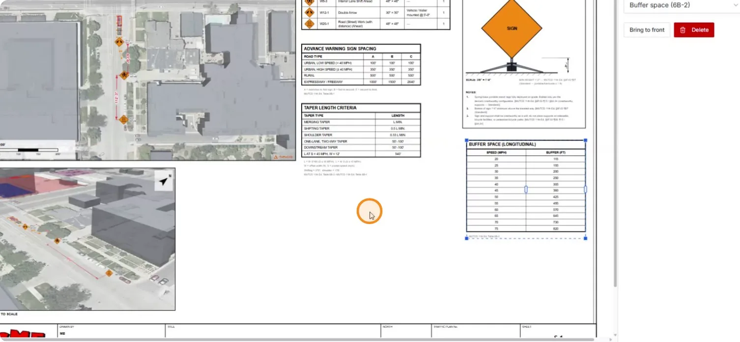
The Buffer Space (6B-2) table placed and selected

8. Mark up the sheet

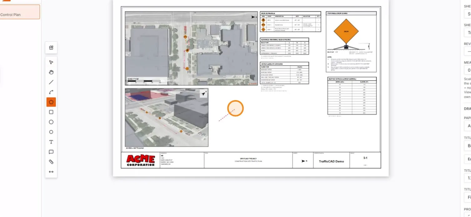
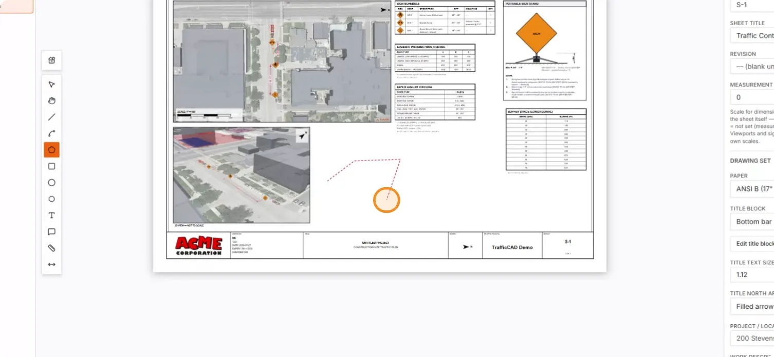
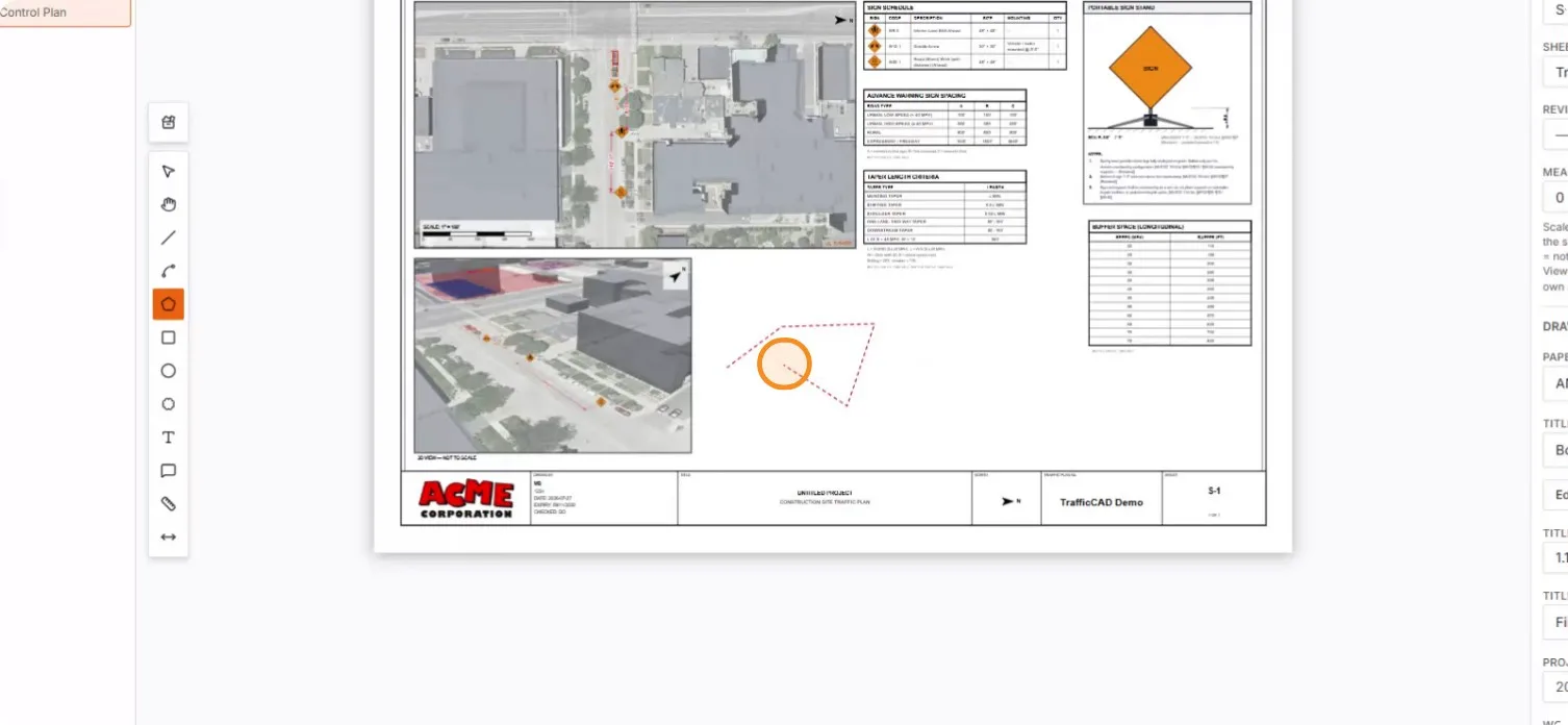
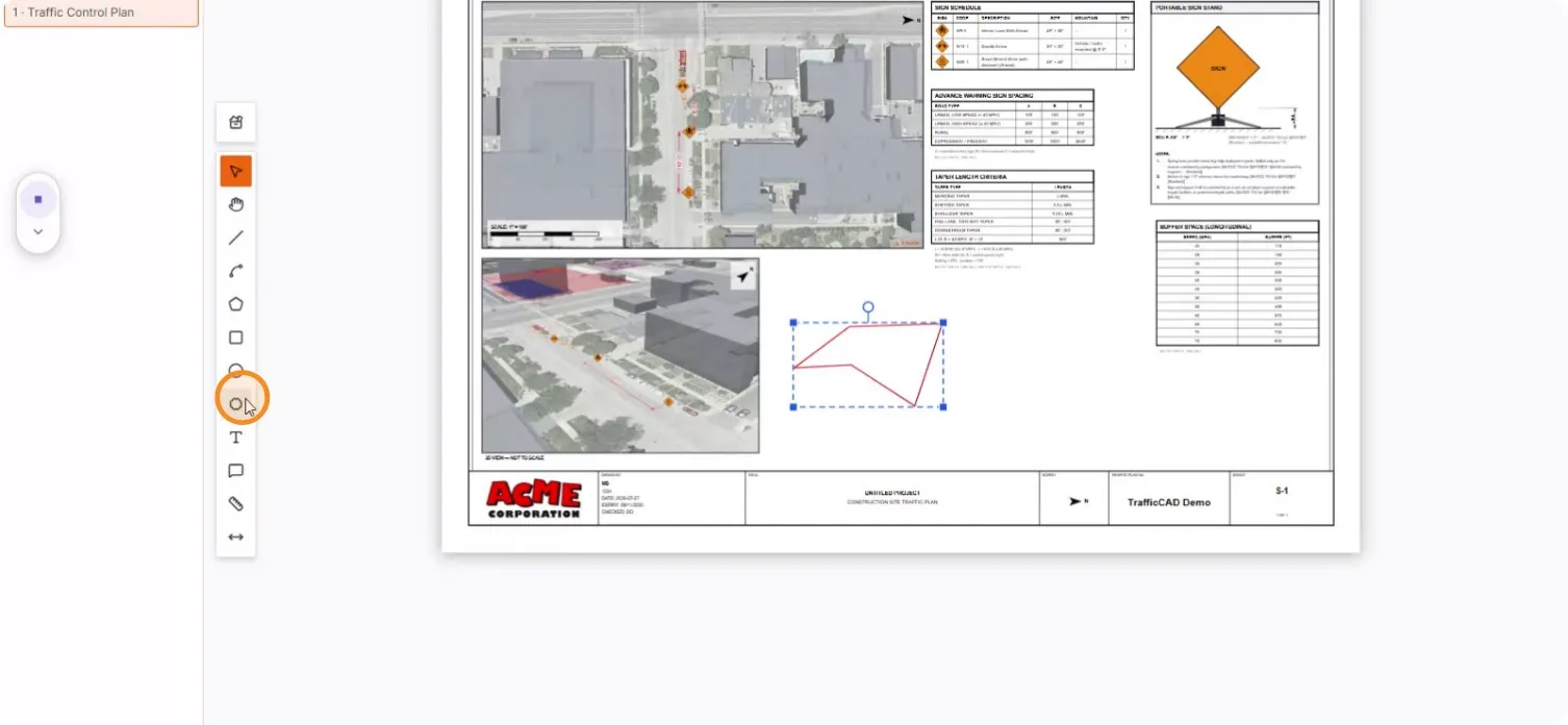
The drawing editor is also a full PDF markup editor — polygons, clouds, callouts, all on the sheet.
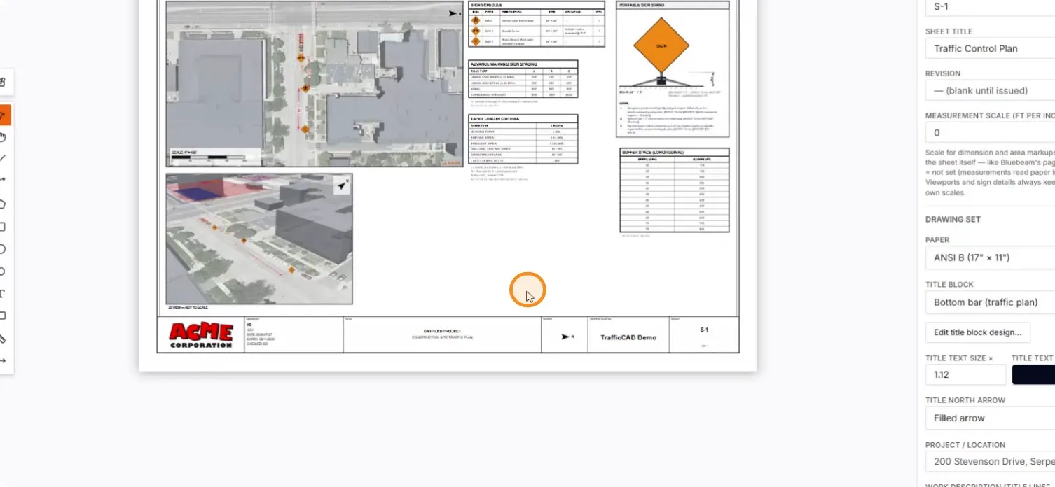
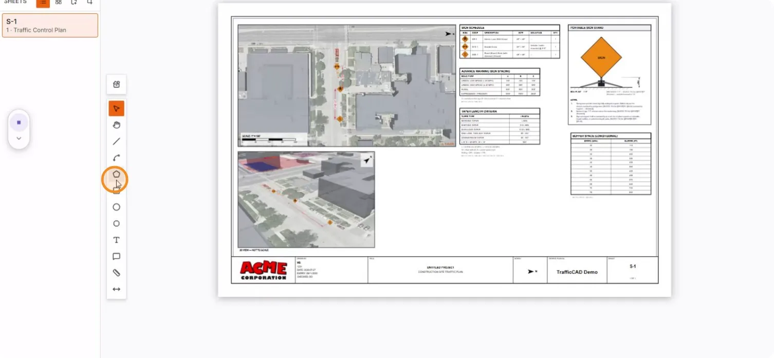
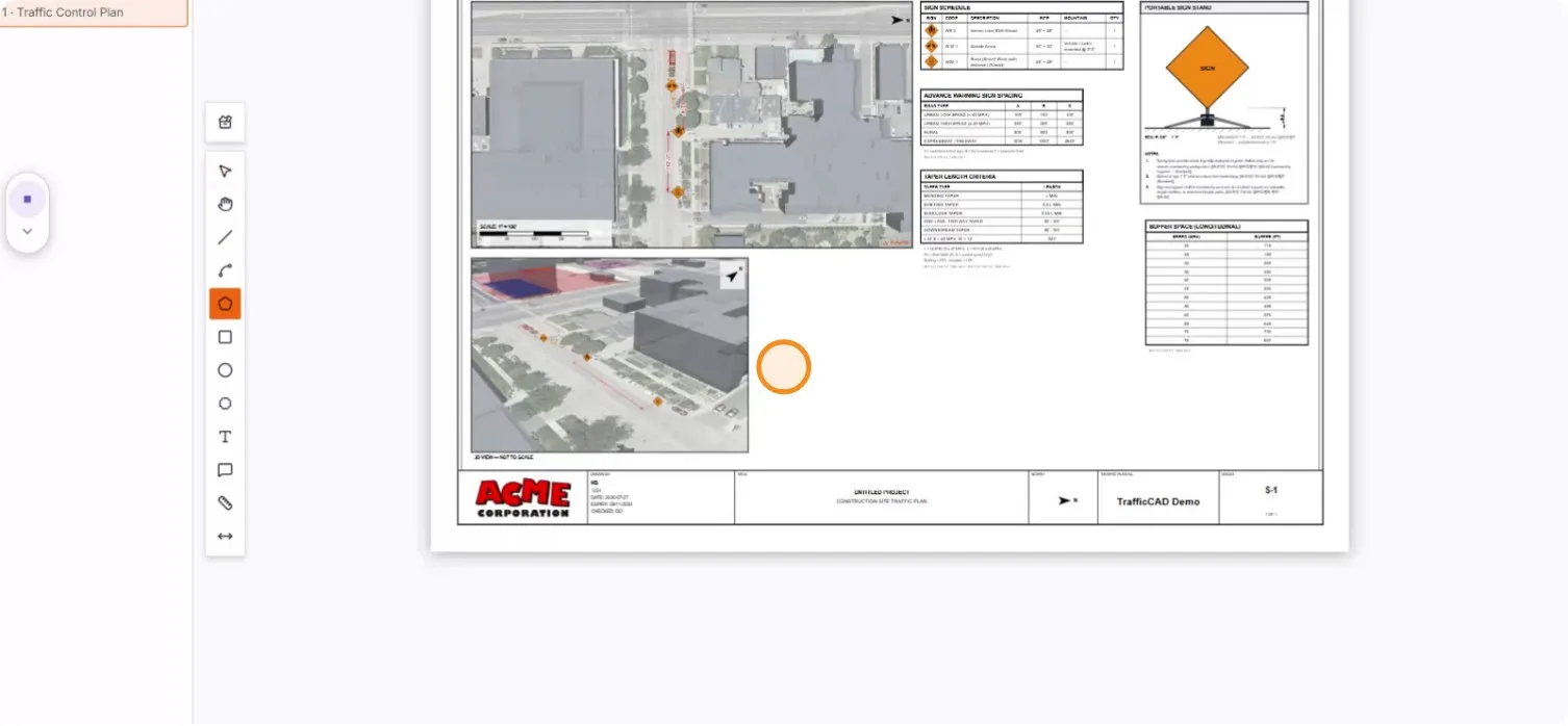
The complete S-1 sheet: plan, 3D view, four tables, detail, title block

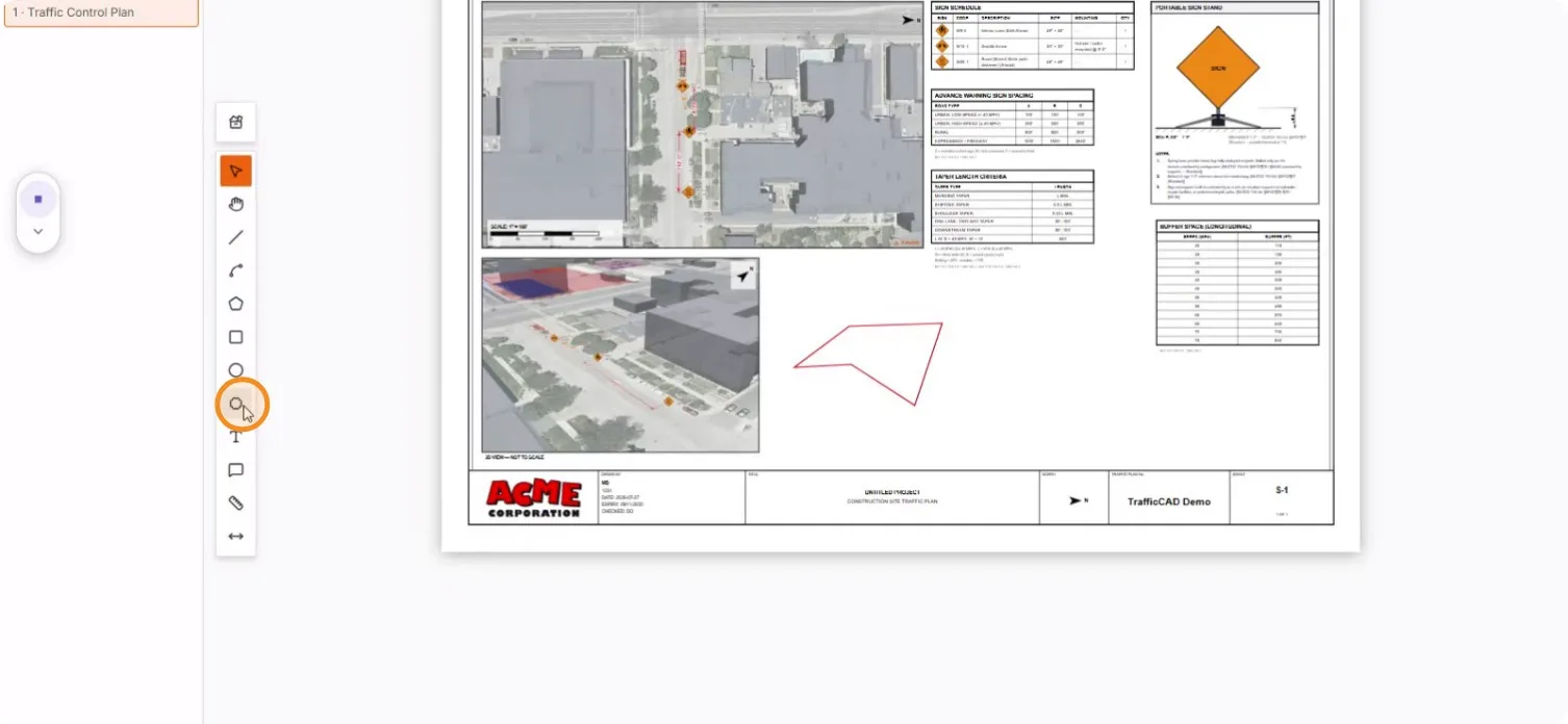
The markup toolbar beside the fitted sheet

The polygon markup tool active

The first dashed segment of a polygon markup

The polygon outline in progress

Closing the polygon

The completed polygon selected, cloud tool under the cursor

The markup in context on the sheet

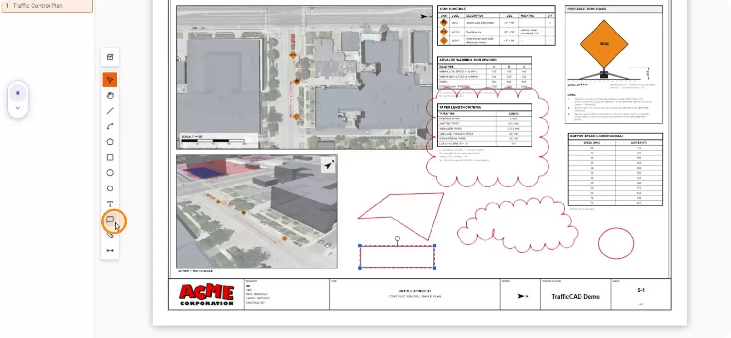
Picking the revision cloud tool

Revision clouds, a circle, and a callout marked across the sheet

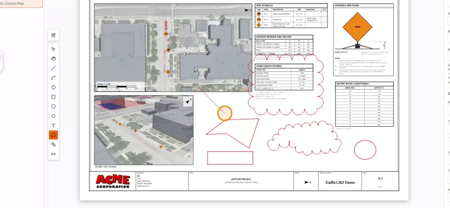
A callout leader dragged from the plan viewport

9. Insert an editable typical application

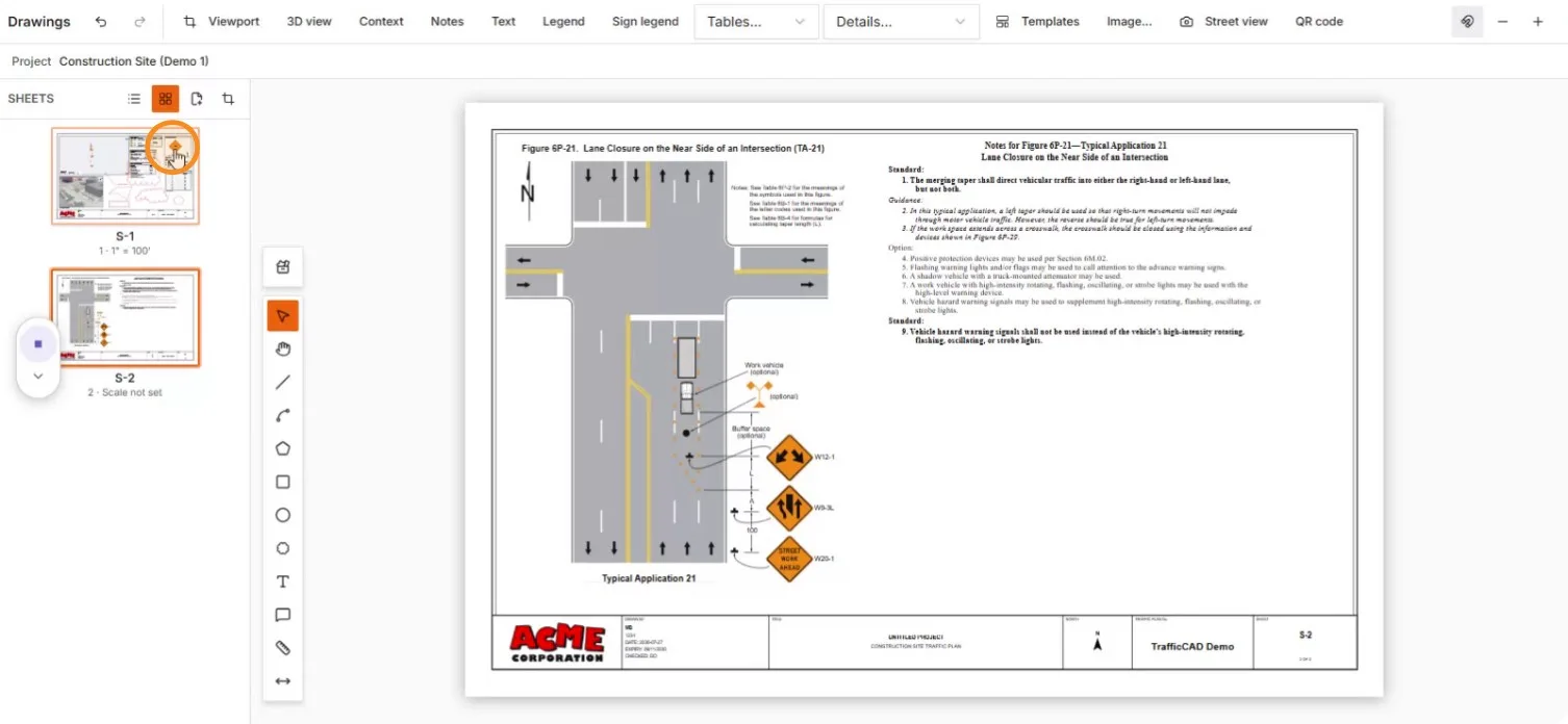
Add a second sheet and drop in a Typical Application from the MUTCD template browser — every template inserts as fully editable vectors.
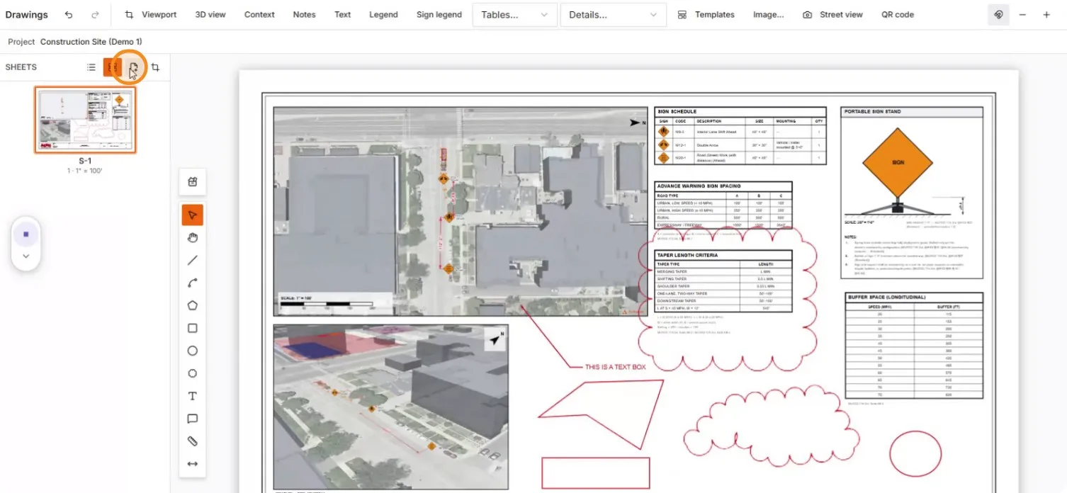
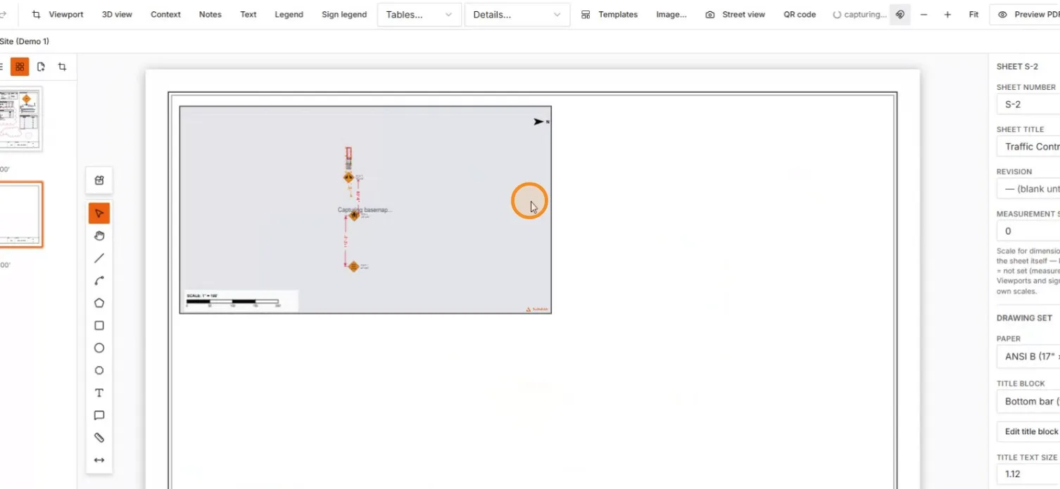
The new-sheet button in the sheets panel

Sheet S-2 capturing its basemap

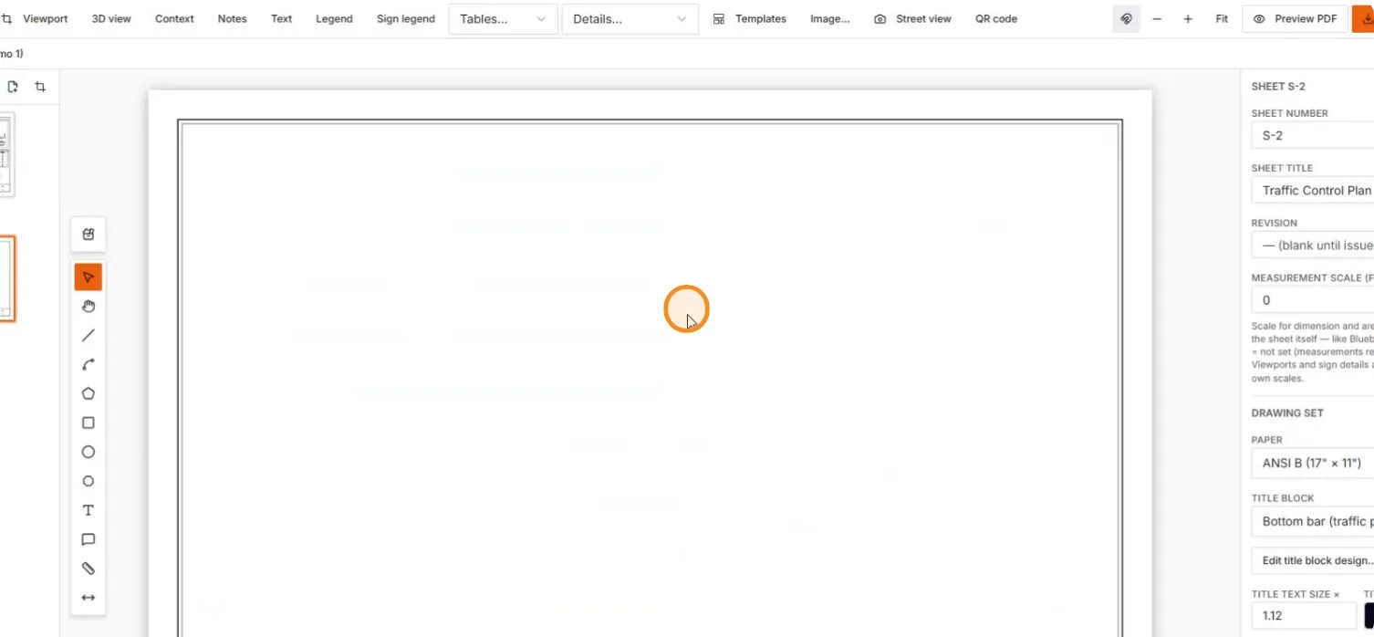
The blank S-2 sheet

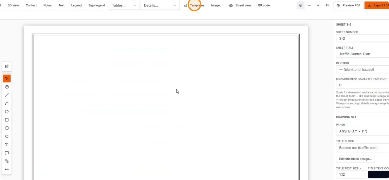
The Templates button on the toolbar

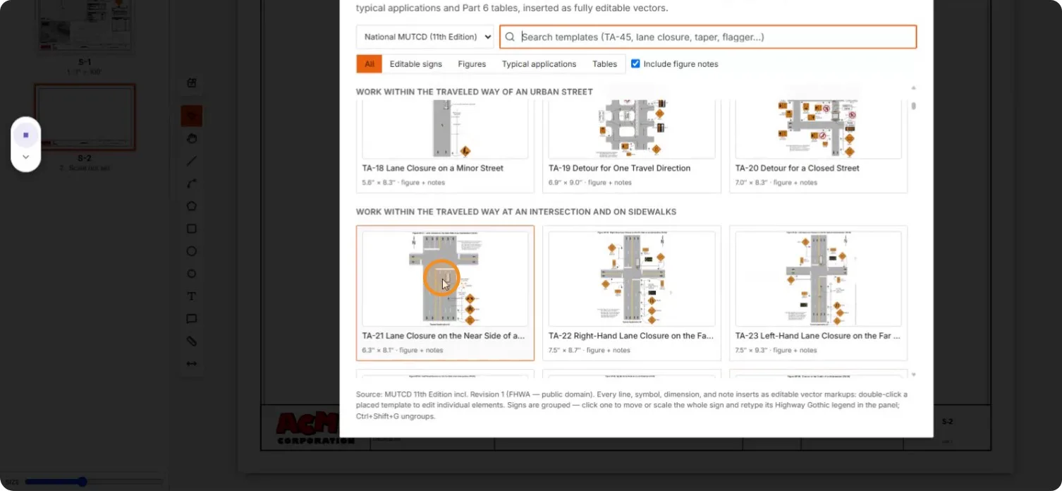
The MUTCD 11th Edition template browser with TA-18 through TA-23

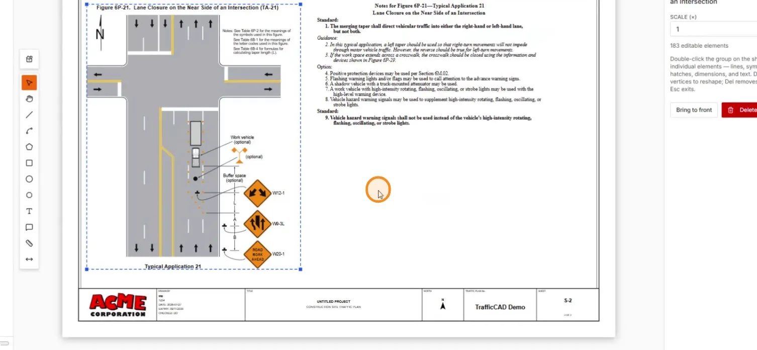
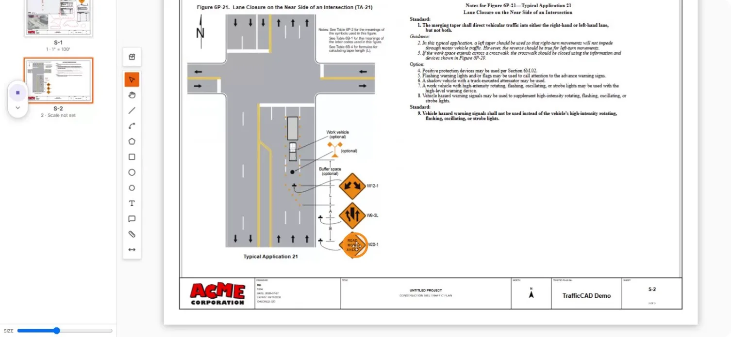
TA-21 placed — the panel reports 183 editable elements

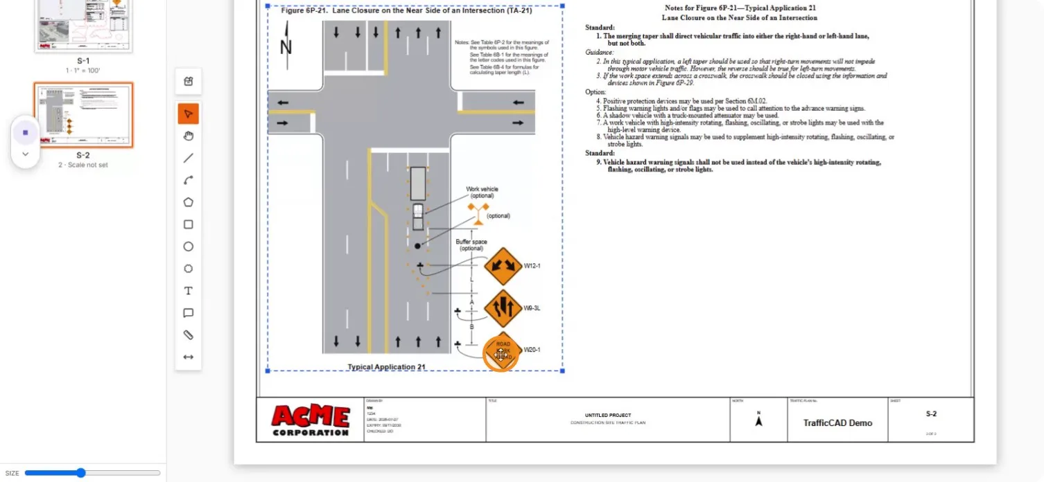
The TA-21 figure with its notes column on sheet S-2

The whole template selected as one group

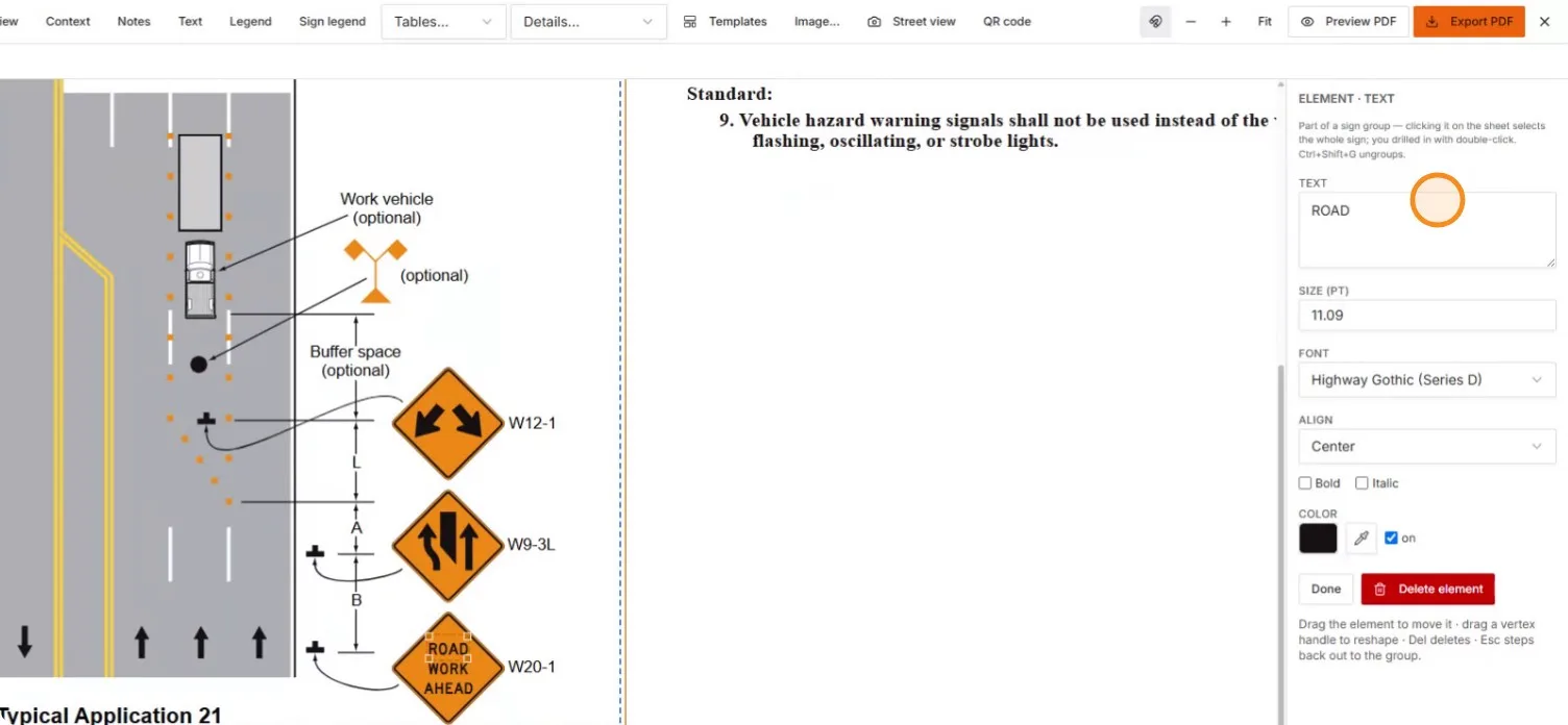
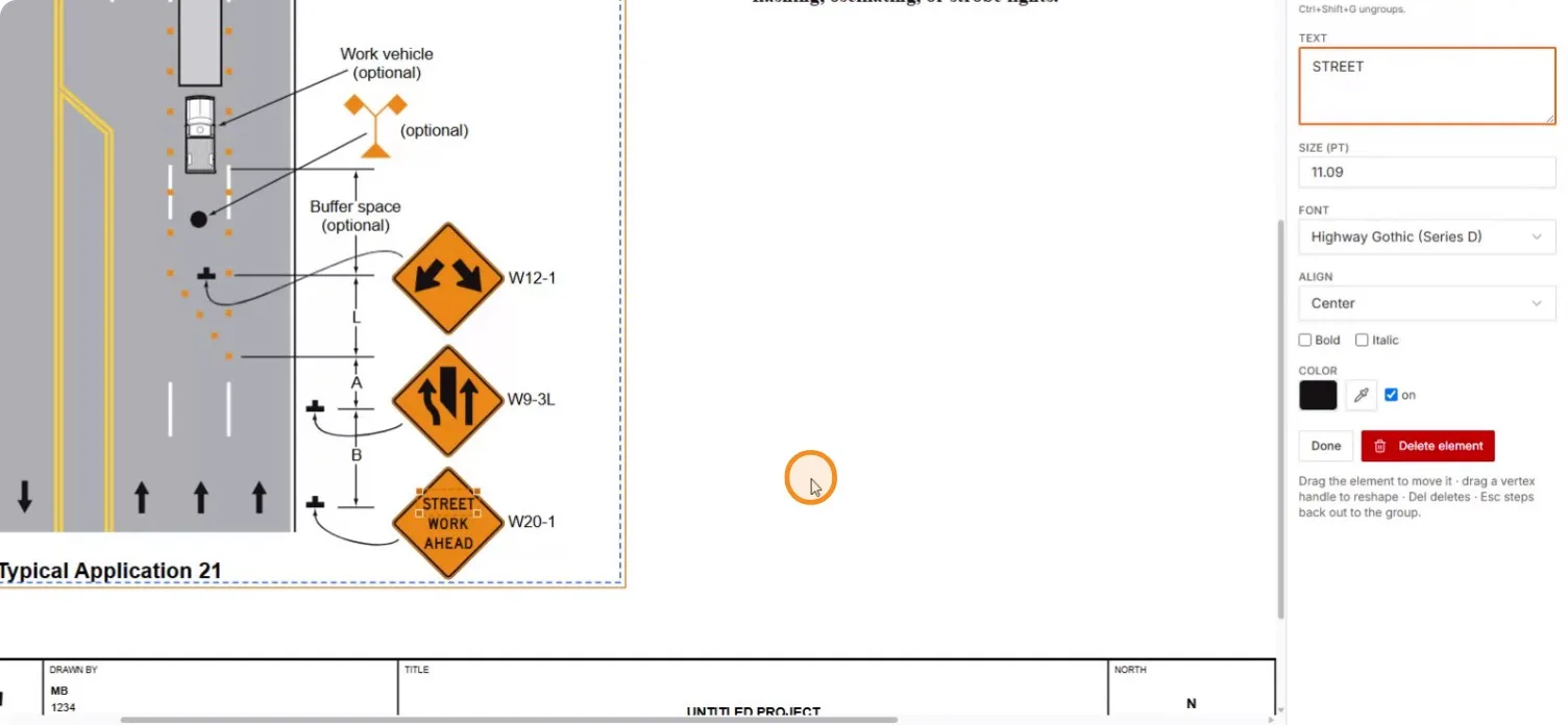
Drill into any element — sign legends edit as text in Highway Gothic.
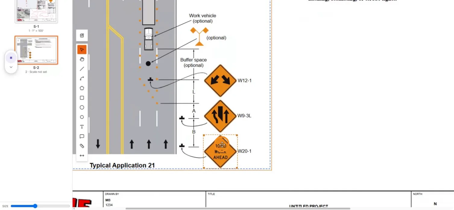
The W20-1 sign group selected inside the template

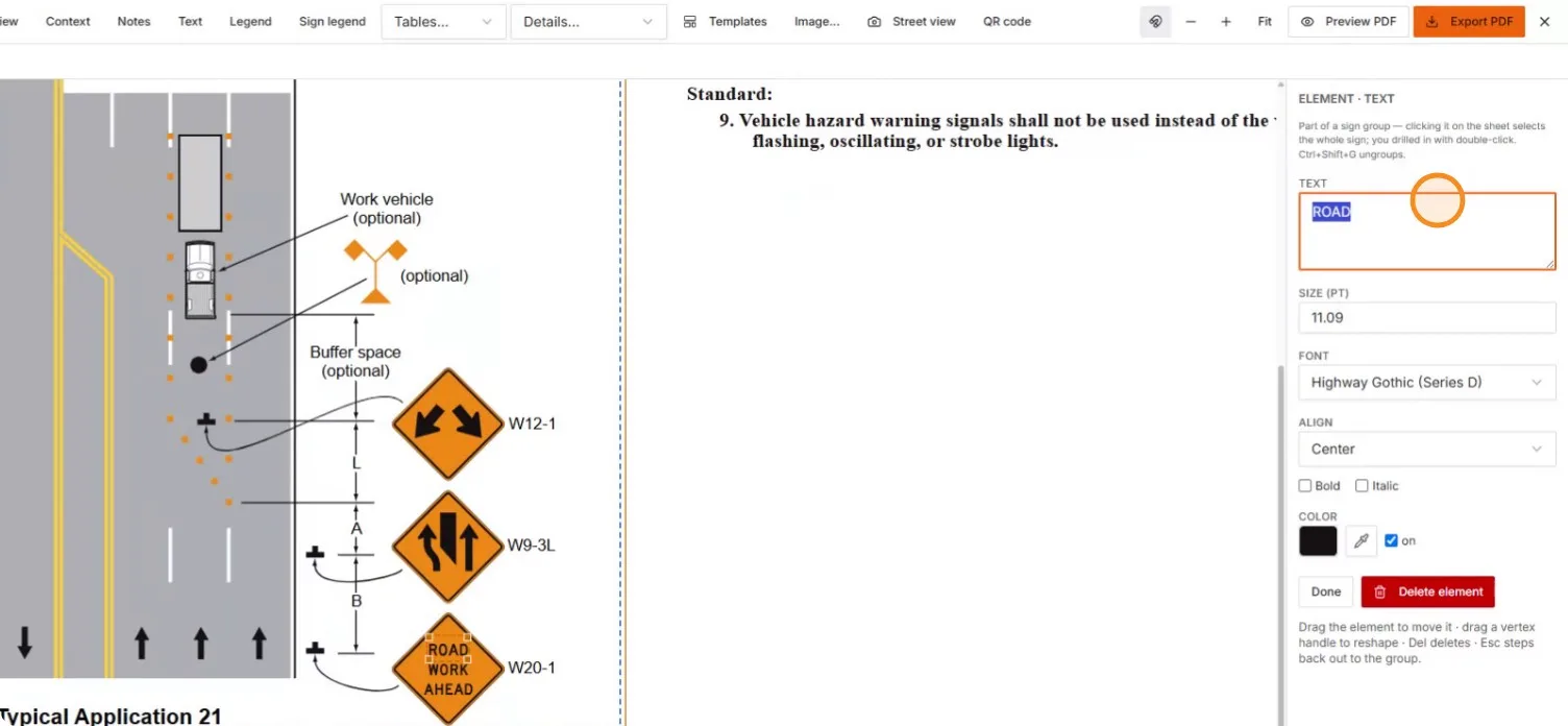
The element text editor on the word ROAD, Highway Gothic (Series D)

The text field selected for retyping

The sign now reads STREET WORK AHEAD

Dimensions and quantities edit the same way.
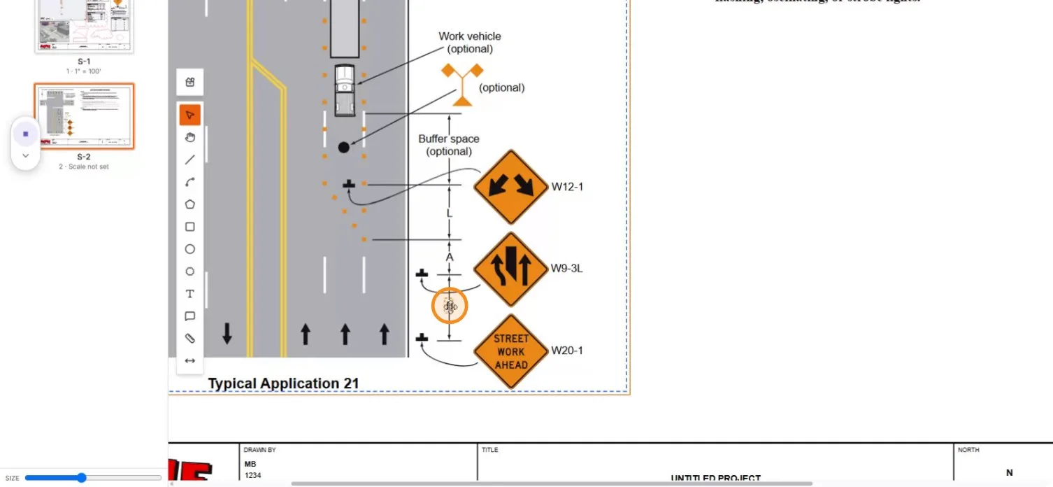
Selecting the spacing dimension between the signs

The finished S-2: edited TA-21, notes, and title block


Reference: Drawings & Plan Sheets · Schedules, Legends & Quantities · Typical Applications & Templates

Next steps: Export & Edit in Bluebeam — everything you just drew stays editable in the PDF.