Channelizing Devices¶
Cones, drums, panels, and barricades — drawn as runs that space devices along a line at the cited MUTCD interval, with true 3D models when the camera tilts. The same device engine powers the chains inside generated TTC plans; this page covers drawing them yourself.
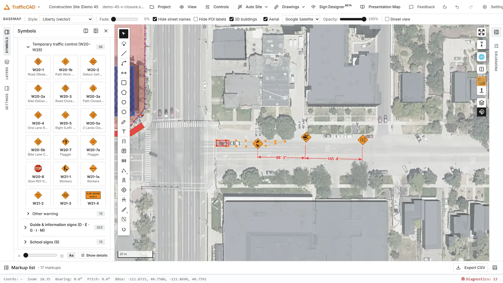
A merging taper built from drums at 30 ft on centre — the run labels its device, count, spacing, and total length.
Drawing a device run¶
- Pick the Channelizing devices tool ("draw the device line — cones/drums/panels/barricades space along it").
- Choose the Device and Spacing in the options block.
- Click the path — along a taper, around a work area — and double-click or Enter to finish.
Devices distribute evenly with a device on each end of the run, the way a crew actually sets them. The single-device button next to the tool places one device at a time (same device choice).
The device palette (MUTCD §6K)¶
| Device | Section |
|---|---|
| Traffic cone (28 in) | §6K.03 |
| Traffic cone (18 in, day/low-speed) | §6K.03 |
| Tubular marker | §6K.04 |
| Vertical panel | §6K.05 |
| Drum | §6K.06 |
| Type 1 / Type 2 / Type 3 barricade | §6K.07 |
| Direction indicator barricade (arrow left/right) | §6K.08 |
| Longitudinal channelizer | §6K.10 |
| Temporary lane separator | §6K.11 |
Longitudinal devices (channelizer, lane separator) chain as 6-ft modular sections along the path, the last section cut to fit — and the lane separator carries its tubular markers.
The Selected channelizing devices editor¶
- Device — switch the whole run's device type.
- Spacing (ft) — blank uses the device default (cones/drums/panels 20 ft, barricades 25–30 ft…). The tooltip quotes the rule: ≤ 1×speed (ft) in tapers, ≤ 2×speed in tangents (§6K.01 ¶04).
- Arrow direction — for direction indicator barricades.
- 3D display — 3D devices when tilted or Flat plan glyphs only.
- Show label — the run's callout, e.g. "Drums — 14 @ 20 ft o.c. (260 ft)", with its §6K citation.
Auto tapers (MUTCD 6B.08)¶
Draw either end of a run with a clear lateral offset — 4 ft or more off the line the run continues on — and the Tapers — MUTCD 6B.08 block in the run's properties unlocks for that end (it stays greyed out until an offset is drawn). The flat part of the run does not have to be perfectly straight: the continuation is measured over a local window, so runs that follow curved roads still read.
Each run carries up to two tapers, one per end: Upstream taper — run start and Downstream taper — run end. Draw in the direction of travel and the names read literally; a run drawn the other way simply uses the other block.
- Set Speed S (mph) — the posted speed limit or off-peak 85th-percentile speed (Table 6B-4's S).
- Pick the Type per Table 6B-3: Merging — at least L, Shifting — at least 0.5 L, Shoulder — at least 0.33 L, One-lane, two-way — 50–100 ft, or Downstream — 50–100 ft.
- Length (ft) prefills with the computed requirement — L = W·S²/60 at 40 mph or less, L = W·S at 45 mph or more, with the offset W read from your drawing — and the note beneath shows W, the drawn taper length, the requirement, and its citation. Edit the length when site conditions call for it (§6B.08 ¶01 allows adjusting near ramps, crossroads, and curves); the panel warns when the value falls below the Table 6B-3 minimum or outside 50–100 ft for the fixed types.
- Click Generate. The drawn end is replaced by a straight taper of exactly that length back from the junction vertex — the offset W and its side stay as drawn, the rest of the run never moves, and the devices re-space along the new geometry. One undo step reverses it.
Change the speed or type later and click Generate again — the taper re-extends from the same junction. Every vertex stays hand-editable afterwards (bend the generated taper onto a curve, nudge the tip); the block re-reads the geometry live as you edit.
Add dimension drops a labeled dimension along the taper — "MERGING TAPER 540 ft" — as a normal dimension markup you can drag, restyle, or delete. Use taper device spacing sets the run's spacing to the §6K.01 taper maximum (1×S ft; tangents allow 2×S, so one spacing keeps the whole run compliant), and the note reminds you that the 50–100 ft tapers use ≈ 20 ft spacing per §6B.08.
2D and 3D¶
In plan view devices draw as the standard MUTCD plan glyphs — unfilled outline squares and bars, the manual's open-legend look — on a dashed device line. Tilt the camera and each station stands up as a true 3D model — cones with reflective collars, drums, striped barricade rails, panels — at real device dimensions, so a drive-through check reads like the street will.
Counts are quantities
Every device in every run is counted individually by the device schedule and the markup list — takeoffs come straight from the drawing.